Allows automation of iOS and Android Apps, as well as iOS and Android browsers.
Appium is a implementation of the WebDriver Wire Protocol, but geared towards automating user interface on mobile devices rather than web browsers.
As such the Appium tool is a specialization of the WebDriver tool in SeqZap, and the documentation of that tool is required reading.
Appium can automate iOS and Android devices, and both emulators/simulators and real devices.
If an app is designed for both Android and iOS – and have a sufficiently similar UIs the same Test Case can test both the Android and the iOS version of the app.
The key to making this happen is to have selectors which are independent of the underlying platform.
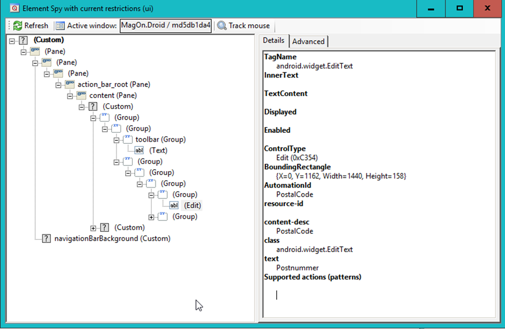
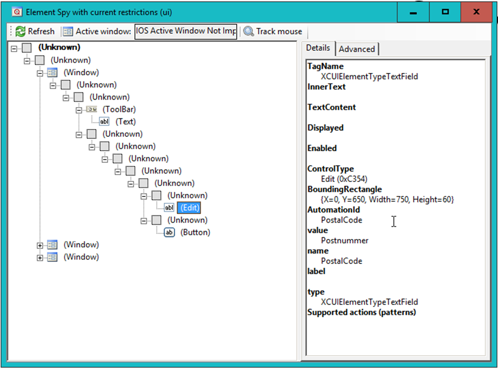
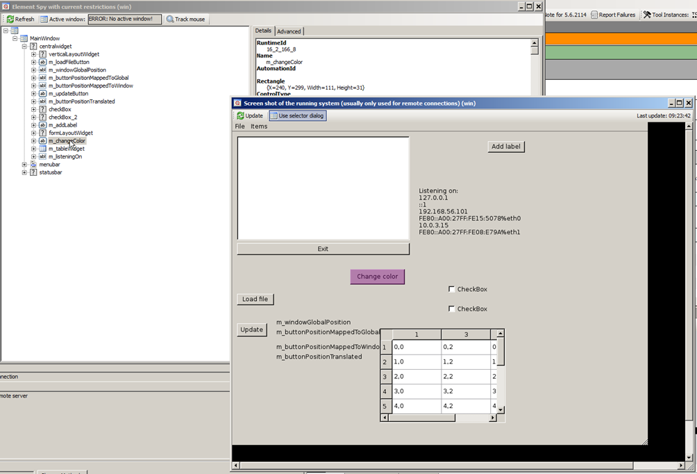
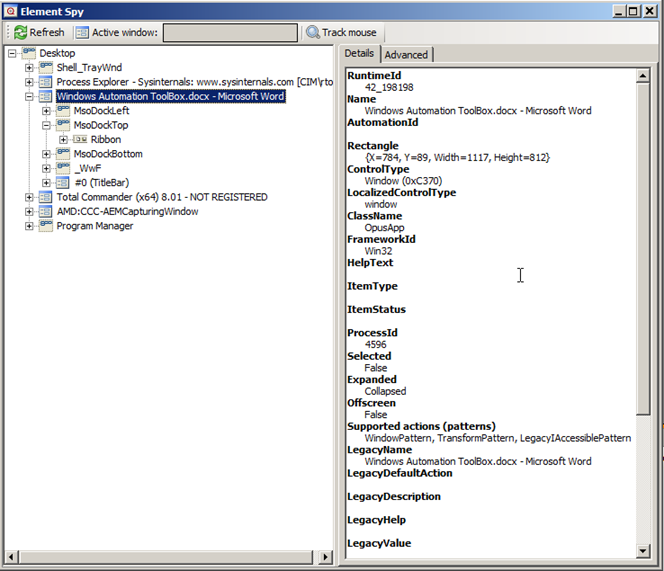
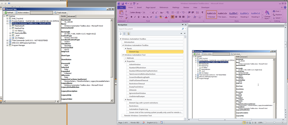
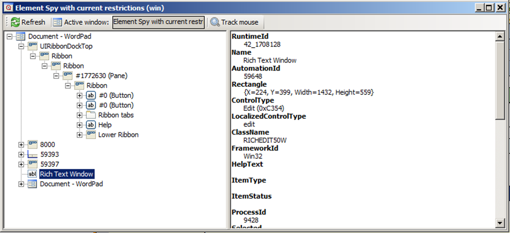
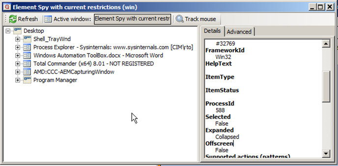
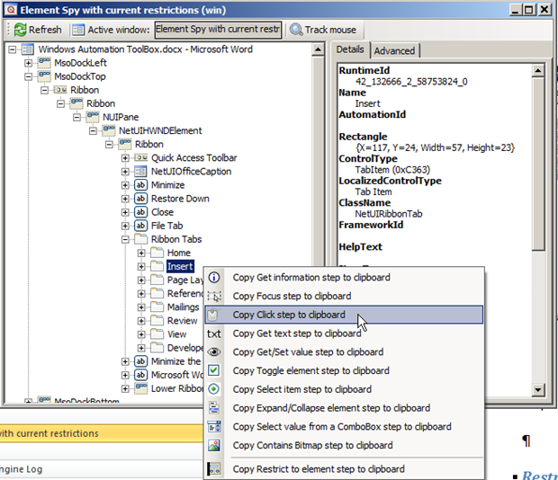
If the UI of an app is inspected, we can see a lot of identifiers which are specific to that particular platform, for instance in this demo app, the PostalCode edit field is shown in the Element Spy panel:
The “content-desc” attribute is an Android specific identifier, but the attribute is also exposed as AutomationId – this is purely something SeqZap does to make it easier to write cross platform test cases.
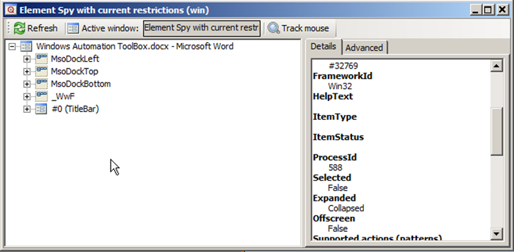
If we take a look at the same PostalCode text field on the iOS version of the same demo app, then we can see that many of the attributes have changed – the Android specific ones – but the AutomationId is still the same.
This is because on iOS the AutomationId attribute is mapped to the “name” attribute.
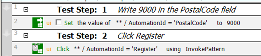
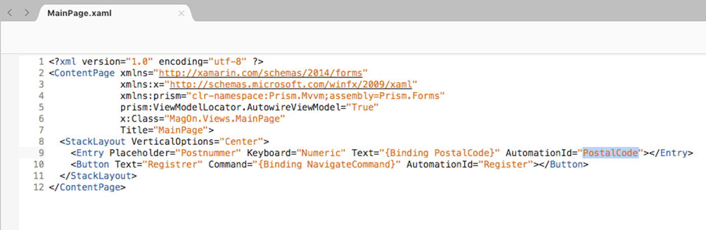
This means that to write cross platform test cases, the test should rely on only the AutomationId as the identifier in the selector, for instance:
This also has the added benefit of making the test run much faster, since using the AutomationId to identify UI elements has special handling in Appium which run much faster.
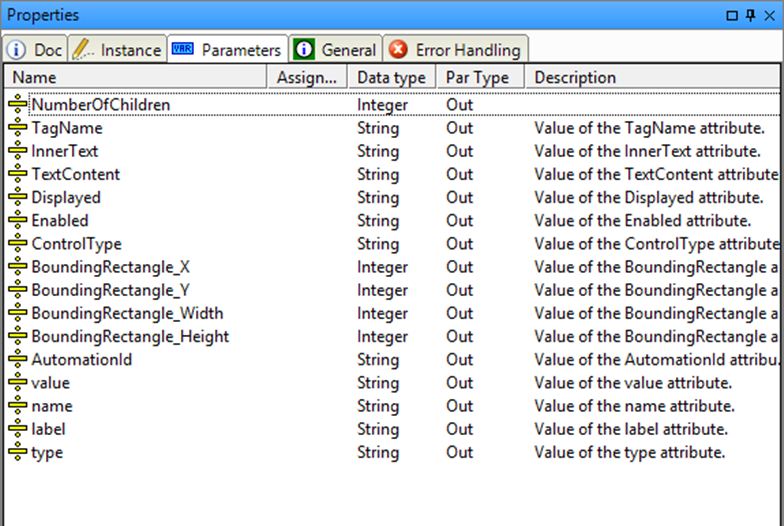
Please note that the use of the Get Information step will break cross-app testing since the Get Information step changes based on the iOS and Android, more specifically the output parameters change based on the plarform.
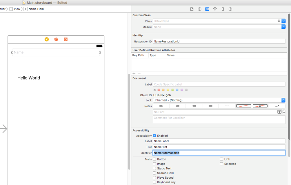
Setting the AutomationId on iOS is done by setting the “Identifier” Accessiblity property by selecting the UI element in the editor and using the Identity inspector in XCode.
In the screenshot above the “Name” text field’s AutomationId is set to NameAutomationId.
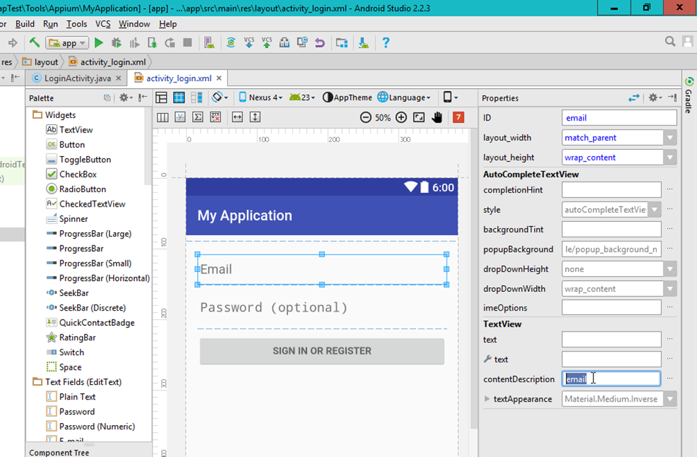
Setting the AutomationId on Android is done by setting the “contentDescription” property using the Layout editor’s Properties view.
Setting the AutomationId when developing apps using the Xamarin.Forms framewok is even easier since the AutomationId attribute in Xamarin already maps to the corresponding attribute on Android/iOS.
This means that the AutomationId set during development can be used during testing also.
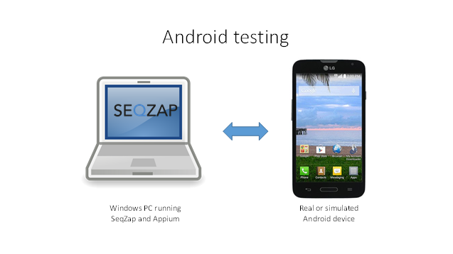
Appium is running on the PC and is responsible for starting the emulator, or connecting to the real device using USB.
Android devices can be automated on the same PC, which is also running SeqZap.
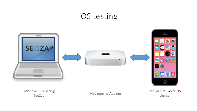
While iOS can only be automated using a real Mac device running Appium.
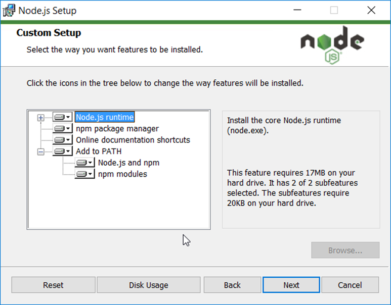
Appium is a Node.js based application, and therefore Node.js must be installed.
When installing Node.js, use the LTS installer and remember to add Node.js to the path.
After installing node.js, Appium can be installed using the Node.js package manager “npm”.
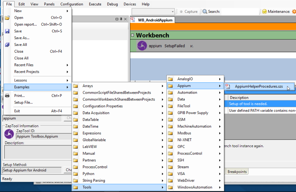
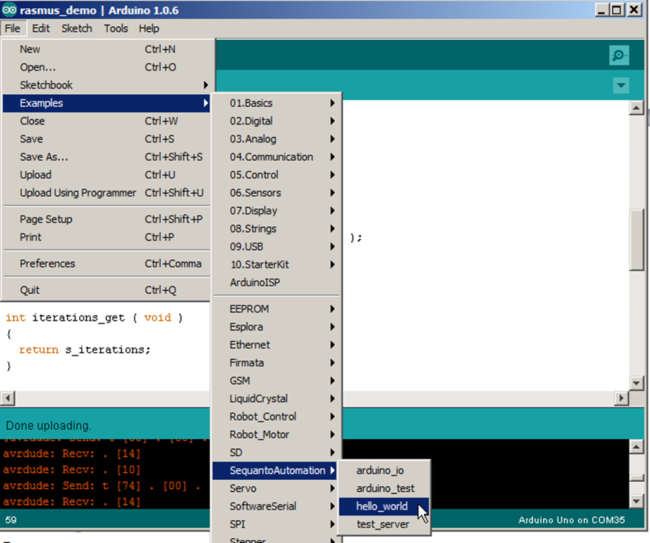
SeqZap comes with a script file to make it easier to install Appium on Windows, it can be accessed by opening the File->Examples->Tools->Appium->AppiumHelperProcedures.szs example
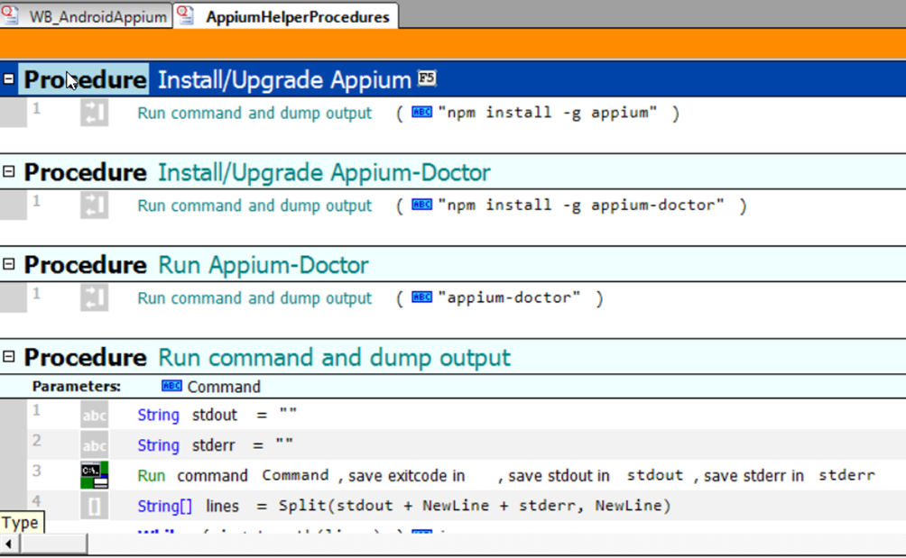
The first two procedures will use npm to install Appium and the diagnostics tool Appium-Doctor using the Node.js package manager.
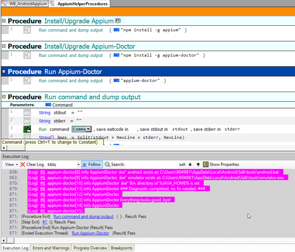
After installing Appium and Appium-Doctor, Appium-Doctor can be used to diagnose whether the installation of Appium is correct. The procedure “Run Appium-Doctor” will run the diagnostics utility and echo the output to the execution log.
After having successfully having installing Appium, the diagnostics tool should report that “Everything looks good, bye!”.
Configuring Appium for Android testing
Windows needs to be configured to find the Android SDK and related tools in order for Appium, and hence SeqZap, to be able to test Android applications.
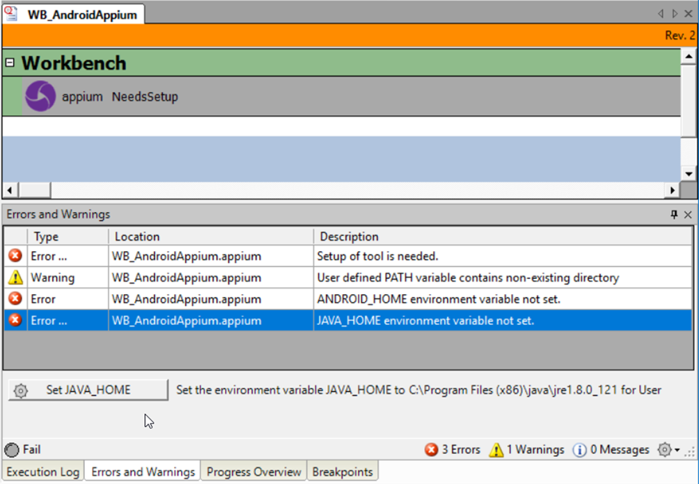
When adding the Appium tool to a workbench, the tool will report parse errors with “auto-fix” buttons to set the relevant environment variables.
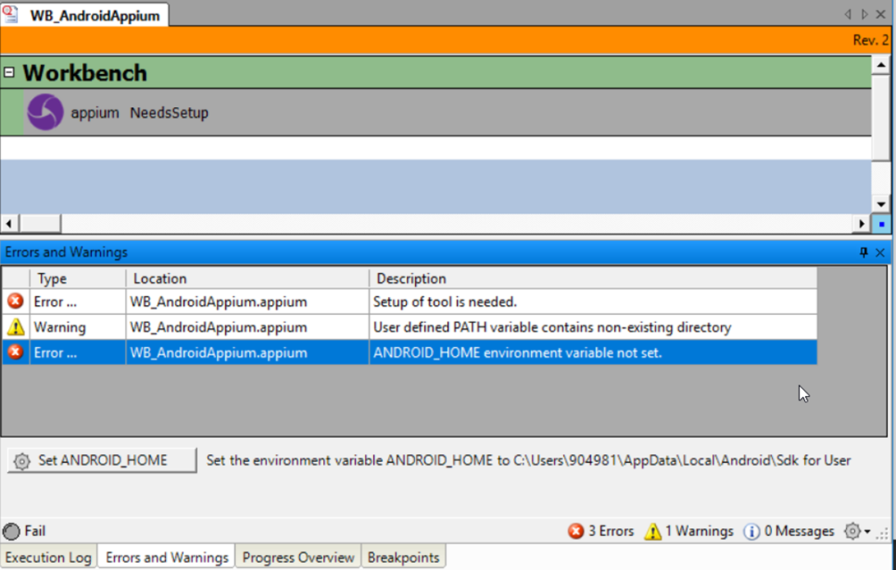
When first adding Appium to the workbench it will report several errors:
If you have Java installed on the PC, SeqZap should show an auto-fix button to set the JAVA_HOME environment variable, otherwise Java can be installed from the java.com website.
The ANDROID_HOME environment variable needs to point to the Android SDK, the easiest way to install the SDK is by installing the Android Studio IDE.
Please note that you may need to restart the PC for the new settings to be registered and the reported Errors & Warnings to be fixed.
Use Appium to automate an Android device (real or emulated)
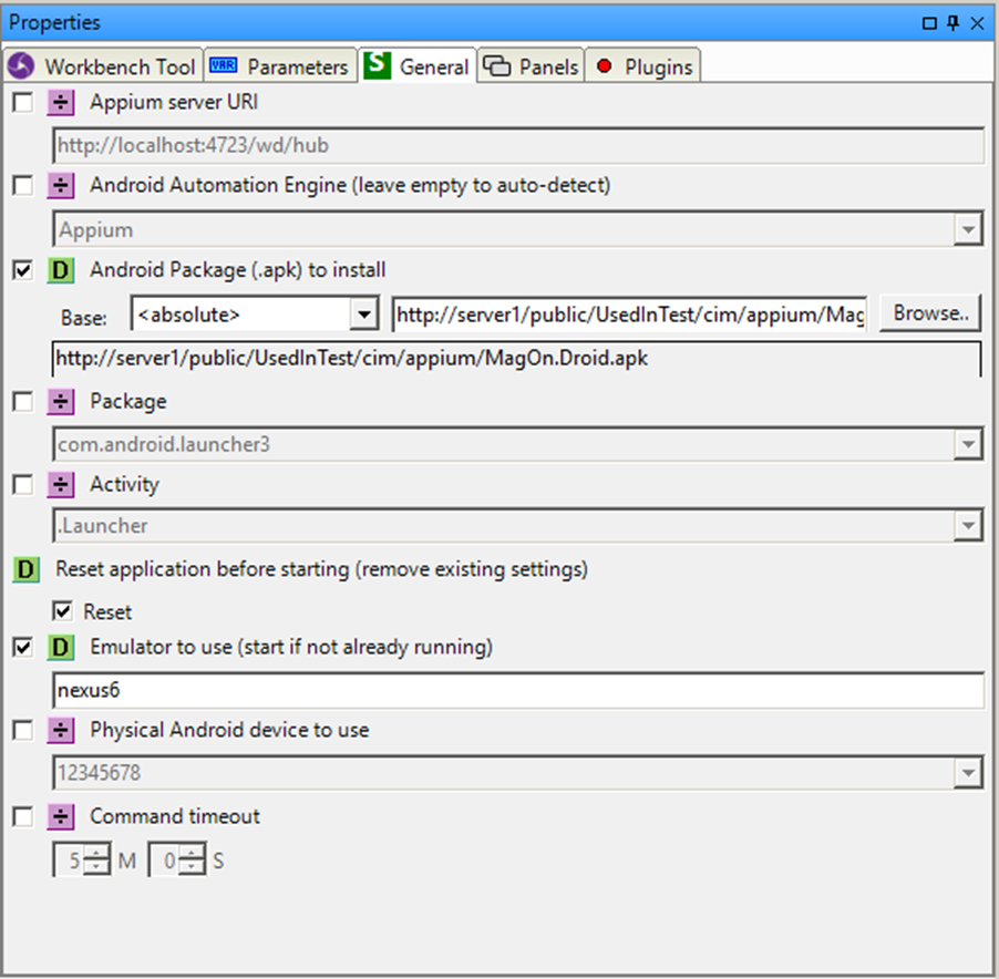
It is possible to specify the address of the Appium server to use, but leaving the checkbox unchecked will make Appium use the local Appium server, or start one if needed.
The specific Android automation engine can also be specified, but it is also possible to just un-check the value and let Appium select the appropriate one.
Next, either the Android package to install and run or the package and activity of an already installed app to run must be specified.
The settings of the app can optionally be reset before starting the test to get a clean and well-defined start point for the test.
After this the name of the real emulator or device to use must be specified, and optionally the ID of the Android device to use.
Finally, the command timeout is set, to allow for slow simulator and Appium startup times we recommend leaving this setting at the default 5 minutes.
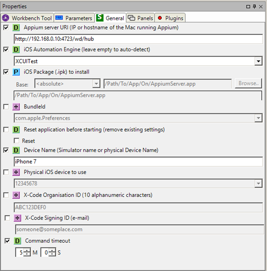
Use Appium to automate an iOS device (real or simulated)
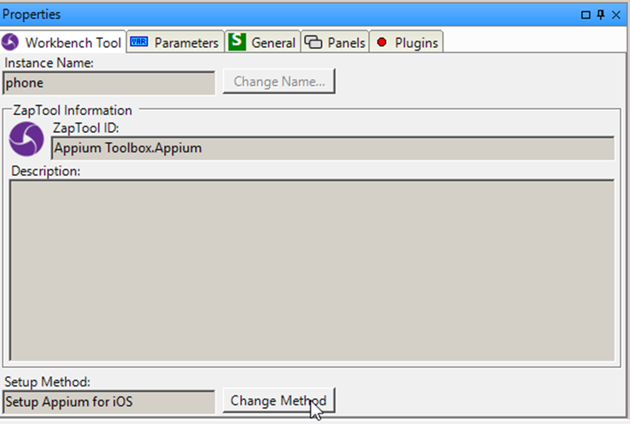
Please note that to change to this Setup Method from the default Android Setup Method, the “Change Method” button on the Appium workbench instance must be clicked:
Because the Appium server is running remotely on a Mac, the IP address or hostname of the Mac must be specified.
The specific iOS automation engine can also be specified, but it is also possible to just un-check the value and let Appium select the appropriate one.
As a rule of thumb iOS versions before version 10 use the Appium engine, while version 10 and later use the XCUITest engine.
Next, either the iOS package to install and run or the BundleId of the already installed app to run must be specified.
Please note that the iOS package for a real iOS device is different than the iOS package for an iOS simulator, this is because the simulator is running x86 code while the iOS device is running ARM code.
The iOS package can also be a zipped archive instead of a complete .app “directory”.
The settings of the app can optionally be reset before starting the test to get a clean and well-defined start point for the test.
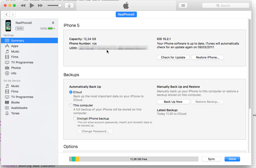
When running on a simulator it is sufficient to supply the name of the simulator to run on, but to run on a real iOS device the ID of the physical device must also be supplied.
This ID can be seen in the iTunes application by navigating to the device summary and clicking the serial number. The ID is a 40 character hexadecimal string.
Because Appium needs to compile and sign the WebDriverAgent which will ultimately driver test on the physical device, the X-Code Organisation ID and X-Code Signing ID needs to be specified.
Finally, the command timeout is set, to allow for slow simulator and Appium startup times we recommend leaving this setting at the default 5 minutes.
Change the current activity on an Android device.
Execute an Appium HTTP request.
This requires expect knowledge of Appium and is almost never used.
Press a button on the connected phone.
Swipe an element to scroll it.
Retrive a file from the connected device.
Save/Upload a file to the connected device.
Set the physical locaion (GPS) of the device (only works on simulators).
The name of the platform which Appium is connected to, usually Android to iOS.
The version of the platform which Appium is connected to.
True, if the connected platform is Android.
Get the unique ID of the connected device.
On Android this will return the activity of the currently focused app.
On Android this will return the package of the currently focused app.
Get the time of the connected device.
Get or set the current network connection status (setting it is only possible on simulators/emulators).
Get or set the current orientation of the screen.
DeviceManager
SeqZap Device Toolbox.
The device manager toolbox is built into SeqZap and allows tools to extend and use SeqZap’s device system.
For a general description of the device system please refer to the SeqZap Reference manual in the Devices section.
Defines a virtual device.
The dynamic Virtual Device Tool is used to create a virtual device in the workbench of a script file. The created virtual device will get the same name as the tool instance.
A virtual device is used to make scripts which use device methods independent of the actual devices used, in other words the virtual device creates an abstract view of the device entities used in a test script.
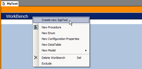
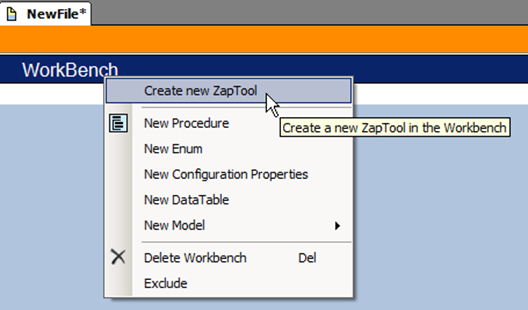
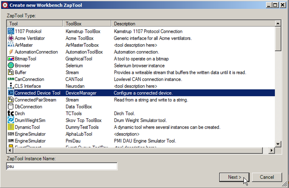
To create a virtual device, right click a workbench and select ‘Create new ZapTool’.
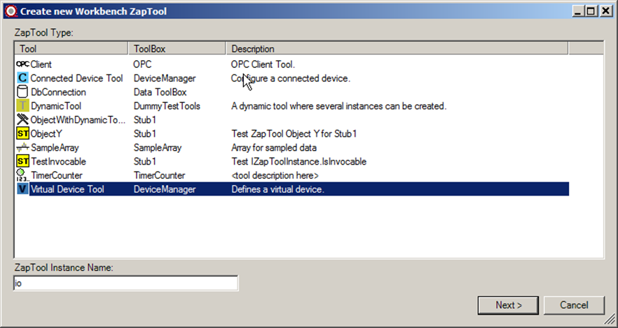
Select ’Virtual Device Tool’ in the dialog and type the name of the tool instance.
Setup virtual device including mappings to physical device entities.
This method is used to setup the list of device entities on the virtual device and to setup the configurations for the linked source device entities.
In each configuration, the source device entity for each virtual device entity must be selected and the setup for each source device entity must also be selected.
It is possible to only use a single configuration or to use multiple configurations. Using multiple configurations allows having several configurations to choose between, but only one configuration can be used at a time.
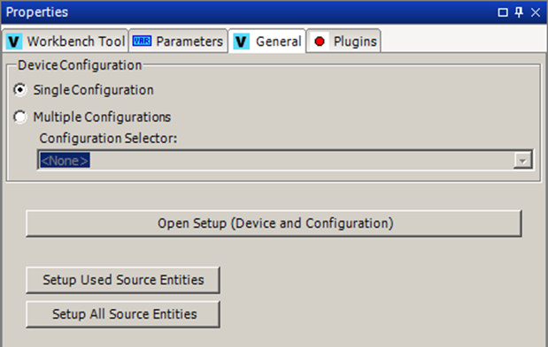
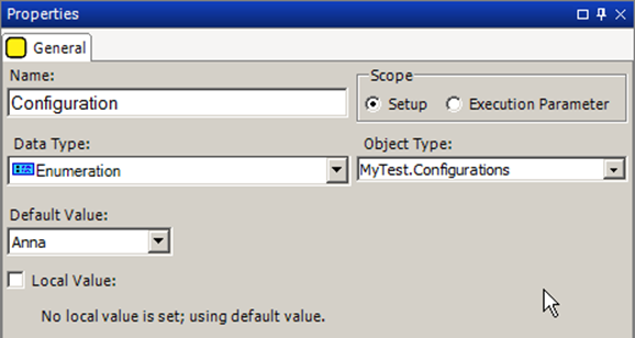
The setup method of the Virtual Device Tool supports any number of configurations. For simple usage the “Single Configuration” option can be selected (default).
Figure 1; Single Configuration chosen
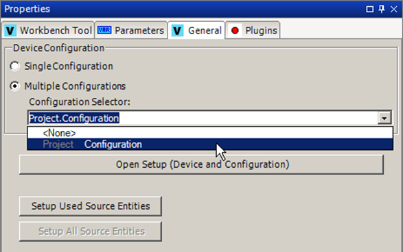
If more than one configuration should be created, the “Multiple Configurations” option can be selected.
When using multiple configurations, a Configuration Property (CP) of an enumeration type must be selected. The selected CP will be used to select which configuration to use for the virtual device. The virtual device will then have one configuration for each value in the enum type of the used CP. Each configuration in the virtual device will have the same name as the associated enum value.
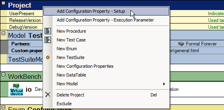
Create a CP for configuration selection by right clicking the project header line and selecting ‘Add Configuration Property - Setup’.
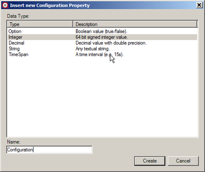
Choose Integer type (will be changed later) and type the name for the CP and press ‘Create’.
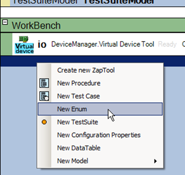
Create a ‘Script Enum’ in the file to enumerate each configuration. Right click the empty line below the workbench and select ‘New Enum’.
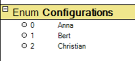
Select a name for the enum and add a value for each configuration.
Select the previously created CP in the file view and change the data type to the new enum. Select also the default configuration by setting the ‘Default Value’ of the CP to one of the values.
The CP can now be selected in the ‘Configuration Selector’ on the virtual device setup page:
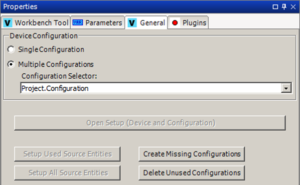
Both when using a single configuration or multiple configurations, the right configurations must be created in the setup data, and any non-used configurations must be removed before the configurations can be edited.
On the setup page there are two buttons for that.
The ‘Create Missing Configurations’ is used to ensure either the single configuration or all configurations in the Multiple Configurations are created.
When switching between ‘Single Configuration’ and ‘Multiple Configurations’ it is necessary to create the configurations that was not created before.
When using multiple configurations it is also necessary to create the missing configurations when adding values to the enum type used by the configuration selector CP.
Likewise the ‘Delete Unused Configurations’ is used when switching between ‘Single Configuration’ and ‘Multiple Configurations’ or when removing values from the enum type used by the configuration selector CP.
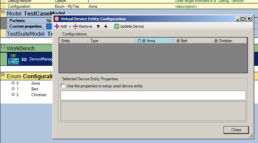
In each configuration, the source entity for each virtual device entity must be chosen and the setup for the source entity must be selected. The setup of the source entity is thereby controlled by the selected configuration of the virtual device.
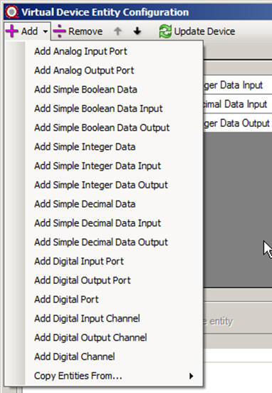
Press the ‘Open Setup (Device and Configuration)’ button on the setup page to open the ‘Virtual Device Entity Configuration’ dialog.
Configure a connected device.
The connected device tool is used for devices which require setup to be useable. For example, a device plugin which require a SeqZap Stream to be defined (e.g. a serial port).
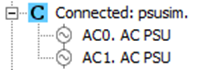
The connected device tool looks like a capital “C” on cyan/turquoise background in the device browser:
Setup connected device.
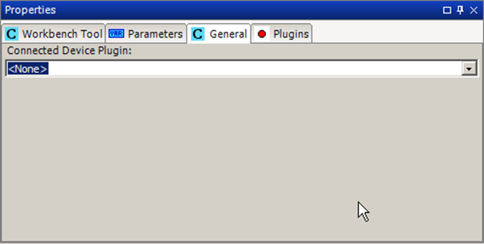
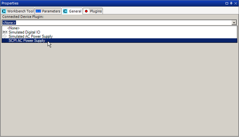
The only setting the connected device tool requires to be setup is the name of the connected device plugin to use.
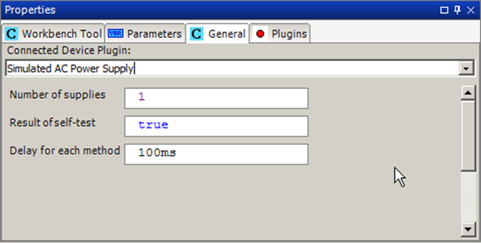
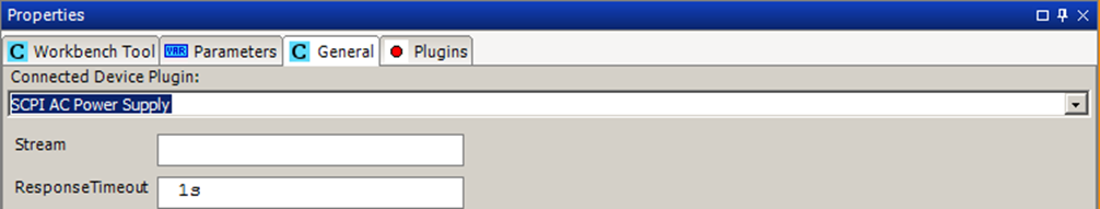
The plugin may add more parameters which need to be defined for the device to be setup.
For a more elaborate example on a connected device, please read the Power Supply section of this manual.
The Title of the used connected device plugin.
GSM
Access to simple GSM terminal hardware
The GSM tool provide support for receiving and sending short text messages (SMS) using a GSM modem connected to the PC running SeqZap.
The tool also provide support for receiving phone calls, although it can only answer the call and get the caller-id, there is only support for sending DTMF data - no support for transferring voice or other data to or from the GSM modem.
Supported modems
Supported modems are:
- Huawei E173
- Tellit GT-HE910-EUD
If you try other modems using SeqZap, successfully or unsuccessfully, please notify us at support@seqzap.com so the list of supported (and eventually unsupported) modems can be updated, thank you!
Gsm Modem/Phone
Provides access to GSM modems and phones via a serial port.
SeqZap comes with an example script for sending and receiving messages located in the Examples\Tools\Gsm directory where SeqZap is installed.
Methods
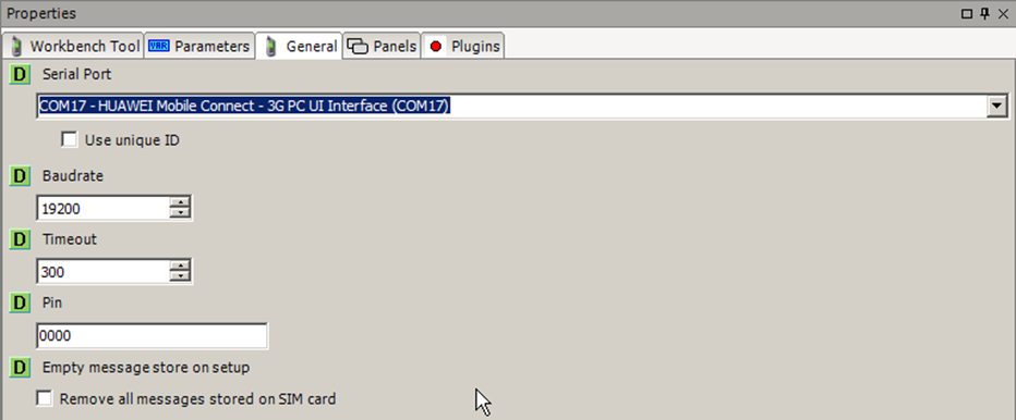
Setup
Connect to GSM modem/phone on a particular port with a particular buad-rate.
During setup the GSM tool will enter the pin code for the SIM card (if needed) and enable caller-id identification when a call is received.
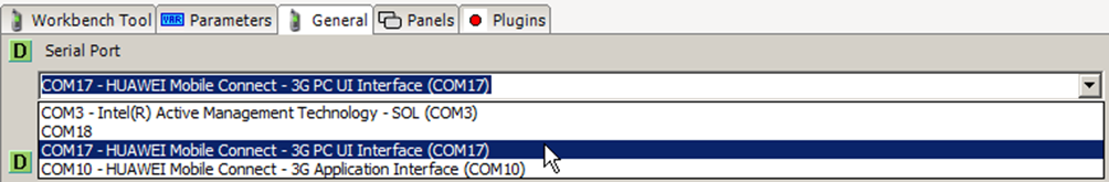
Some modems register more than one COM port on the PC where it is connected, for instance, a Huawei E173 modem will register two COM ports:
The easiest way to find the correct port is just by trial and error, by trying setting up the tool, for the Huawei E173 modem the correct COM port is the “PC UI Interface” one.
Send SMS
Send a message to a recipient.
Send an SMS with the given text to the given number.
Receive SMS
Get all the SMS messages that has been received since the last time Receive SMS was called.
Receive all the incoming SMS messages from the modem.
Wait for call
Wait for someone to call the phone/modem (does not answer the call).
Wait for a call to be made to the modem, when the call is received the caller-id is also returned.
Answer call
Answer an incoming call
Answer a waiting call.
Hang up
Hang up phone/modem
Hang up an existing call.
Make a call
Send DTMF
Change length of DTMF tones
Properties
Manufacturer
The manufacturer of the modem.
Model
Revision
The revision of the modem.
SerialNumber
The serial number of the modem.
PinStatus
Whether the modem is waiting for the pin to be entered.
SupportedCharacterSets
The list of character sets supported by the modem.
CurrentCharacterSets
The current character set used by the modem.
Panels
Message Store
List the messages saved on the phone/modem/SIM-card
The message store allows browsing of the messages stored on the SIM card and modem.
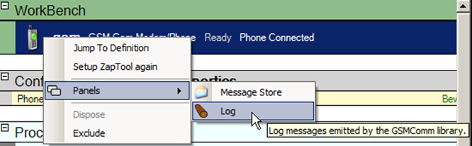
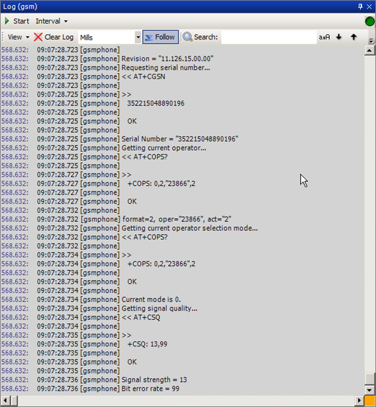
Log
Log messages emitted by the GSMComm library.
The log panel is useful when trying a new modem model, it will show the exact AT commands sent and received from the mode.
MIDI
MIDI Tools.
Send and receive MIDI-messages and streaming via plugins in SysEx-messages.
Device
A base tool for MidiInputDevice and MidiOutputDevice
Methods
SetupDevice
Basic setup of a MIDI device
Open
Close
Tool for receiving MIDI messages.
Basic setup of a MIDI device
Start receiving MIDI messages.
Stop receiving MIDI messages.
Waits until the input device starts receiving messages.
Waits until the input device does not receive any more messages.
Piano Panel for playing notes through a MIDI Output
OutputDevice
Tool for sending MIDI messages.
Methods
SetupDevice
Basic setup of a MIDI device
Open
Close
SendSysExMessage
Panels
MIDI Piano Panel
Piano Panel for playing notes through a MIDI Output
MidiStream
Stream that uses MIDI as lowlevel protocol.
Methods
Open
Close
Read String
Read a string from a stream
Read Line
Read a line from a steam.
Read Byte
Read a single byte from a steam.
Read Until
Read from a stream until a given string is read.
Read Until Silent
Read from a steam until no data has been received for a given time.
Write String
Write a string to the stream
Write Binary Data from string
Write binary data to the stream. The data is taken from a string listing the binary values. To decode the data string a decoder for the specific format must be selected.
Write Text
Write multiple lines of text to the stream
Flush
Flush read/write buffers of the stream
SetupStream
Basic setup of a MIDI stream (through SysExMessages)
Request and wait for response
Read Bytes
Write Bytes
Read XML
Panels
Data Counter
Provides a byte counter to observe how many bytes are read/written
Data Sniffer
Sniff the read/write data of a stream.
MIDI Stream Test Panel
A UI for testing a MIDI Stream
Data Commander
Properties
WriteTimeout
ReadTimeout
IsOpen
DataAvailable
SupportsDataReceived
Sequence
Tool for a sequence of MIDI messages.
Methods
Open MIDI file (*.mid or *.syx)
Open a MIDI file (*.mid or *.syx).
OpenFile
Open a MIDI file (*.mid or *.syx).
Save to MIDI file (*.mid or *.syx)
Save sequence to a MIDI file (*.mid or *.syx).
SaveFile
Save the sequence in a MIDI file (*.mid or *.sys).
Play
Plays the sequence using the specified output device.
Record
Records from the specified input device to the sequence.
Stop
Stops playback or recording.
Continue
Continue playing or recording
Clear
RemoveTiming
Remove timing in all tracks
Properties
WorkState
Panels
MIDI Sequence Viewer
Lists all messages in the tracks in a MIDI sequence.
NI-XNET
National Instruments CAN/LIN/FlexRay bus support using the NI-XNET driver.
The NI-XNET driver supports access to high-speed serial buses such as CAN/LIN/FlexRay by putting the actual bus logic and device reading/writing in dedicated hardware outside the PC. This allows SeqZap to support the real-time timing of these serial buses.
The NI-XNET driver must be installed for the tool to work, the runtime variant is sufficient and version 16.0 is recommended, it can be downloaded here:
http://www.ni.com/download/ni-xnet-16.0/6131/en/
NI-XNET
Access the NI-XNET using a database definition file such as a CAN DB (.candb) or a LIN Description Format (.ldf).
The database to use is specified as part of the setup of the tool, please see the Setup method for more.
Please see the parent NI-XNET toolbox description for information on driver installation and so on.
An example script using the NI-XNET device is available in the Examples menu under File -> Examples -> Tools -> NI-XNET.
Methods
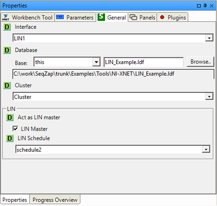
Setup
Connect to an NI-XNET device and use a database.
The setup methods is where the database to use is defined, for example, the CANdb database file to use, the Cluster in the database to use must also be specified. For database formats (like LIN Description Files) where a Cluster is not used, a default Cluster of “Cluster” will be automatically created by the NI-XNET driver.
The Setup method also provides settings for specific interfaces, where specific configuration is needed to behave properly on the bus.
LIN
SeqZap can be configured to act as a master on the LIN bus using a particular schedule defined in the LIN description file.
LIN busses must have a single master which is responsible for polling the various slave nodes at a given interval.
When setting LIN as master, the interface will also send wake-up frames on the LIN network to wake up any sleeping slaves.
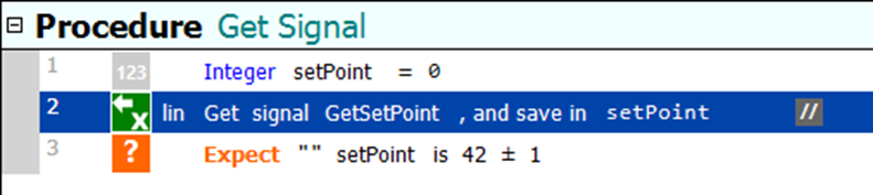
Get Signal
Get the value of a signal.
The data type of the returned value will be an integer or an decimal value, depending on the signal.
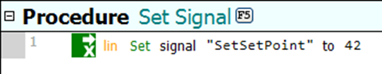
Set Signal
Set the value of a signal.
Properties
LinMaster
If true, SeqZap will act as a master on the LIN bus.
Panels
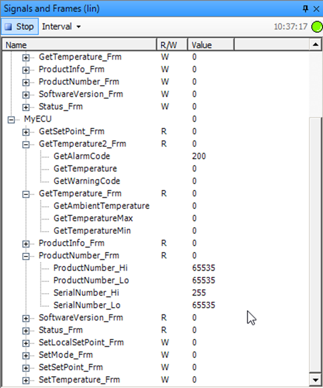
Signals and Frames
The signals and frames panel shows a read-only view of all the signals available grouped by the frame which contain the signal.
Generally it is easier to ignore the frames and just use signals when writing and debugging tests, which is why the Signal panel is the recommended panel – it also allows writing signals instead of only reading them.
Signals
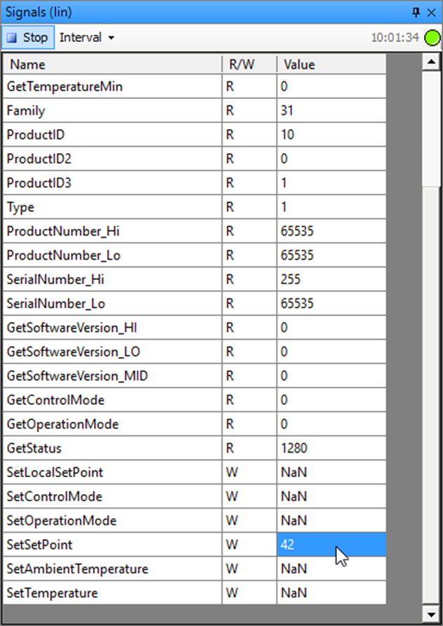
The signals panel will read signal values from the slaves and present them to provide an easy view of the current slaves when debugging a test or just experimenting with the slaves.
Writable signals can also be changed in the panel by selecting the value cell, typing and hitting the “Enter” key when done.
Writable signals have the value NaN until the signal is written to, either from a panel or from a script.
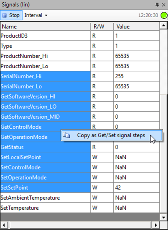
Copy/Paste
The Signals panel supports Copy/Paste from the panel and to the script file, this feature makes it very quick to write scripts based on the actual values in the slave.
Start by selecting a number of signals to copy and then right-click the selection and select “Copy as Get/Set signal steps)”
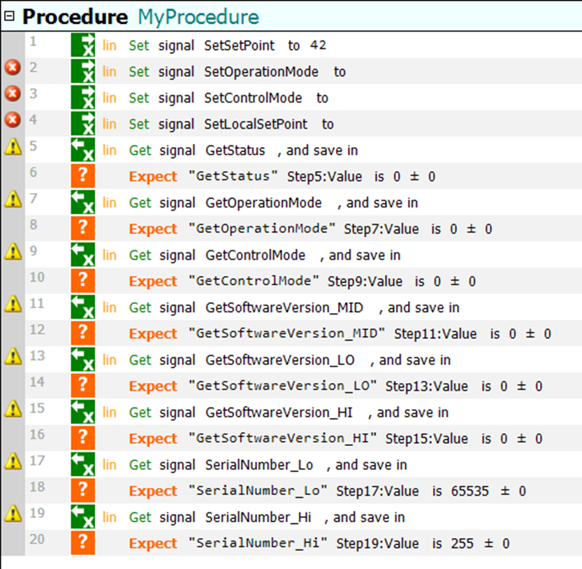
Then select a procedure in a script file and press Ctrl+V (or right-click and select Paste from the context menu).
This will insert “Set Signal” steps for the writable signals, notice that the signals which have not yet been set are copied without a value and therefore the parser reports an error.
Readable signals are copied with an associated numeric expect step which expects the signal to have the current value when the script is executed, this step can just be deleted to just get the signal without expecting on the value.
OPC
Tools for communicating with OPC servers.
The OPC toolbox contains tools related to the OPC (OLE for Process Control) protocol.
The toolbox is based on the Quick OPC component from OPC Labs and SeqZap includes a license for QuickOPC allowing its use in SeqZap.
Disclaimer: CIM Software Testing are NOT OPC experts. Making it possible to connect to an OPC DA server on a remote machine requires OPC, DCOM and Windows administration skills. Please contact an OPC expert or your IT support for help setting up your PC for access to remote OPC servers.
Troubleshooting OPC problems
Connecting
Since OPC is based on COM and DCOM (Distributed COM), the error codes reported by OPC are usually hard-to-understand opaque COM error codes 0x8000????.
A common situation is that the OPC server is running locally on the machine, but SeqZap can still not connect or find the server (called browse the serer in OPC terminology).
A common way to fix this is to by-pass much of the DCOM permission system and connect directly to the local OPC server by setting MachineName to the empty string, instead of using localhost.
Authentication and Permissions
A common situation is that SeqZap is running automated tests on the command line by being invoked by a build system slave (for example Jenkins) running as another user than the primary user account on a machine.
COM and DCOM also brings an authentication and permission system which is different from normal permission systems, at least, when it comes to error messages.
To help debug these issues the OPCToolTester.exe file shipped with SeqZap in the ZapTools\OCP_DOTNET451 folder. This program will connect to the local OPC server and list all servers and fields found using the local OPC server and writes them on the console (standard output), this makes it suitable for running as the SERVICE user where SeqZap Studio cannot run due to user interface limitations.
The following section documents the arguments that the OPCToolTester.exe can take.
The OPCToolTester.exe is located in the ZapTools\OPC_DOTNET451 folder, in the installation folder of SeqZap (usually C:\Program Files (x86)\SeqZap).
The OPCToolTester.exe will list all servers discovered by the local OPC server, and list the fields (leaves) found on those servers.
The OPCToolTester.exe connects to the OPC server on localhost through DCOM by default, but this can be changed by using the –h <hostname> argument – to connect to the local OPC server using normal COM, the empty hostname can be specified by using –h “”.
By default the OPC values are only listed, but not read, to read the values the –r argument can be added.
OPC DA Client
OPC DA Client Tool.
The OPC Client tool is a tool for getting and setting item values from a connected OPC DA server.
The tool includes an abstraction layer to be able to assign the OPC items descriptive names to improve script readability and maintainability. By doing that, it is also possible to re-map items to another “physical” OPC item without having to change existing scripts.
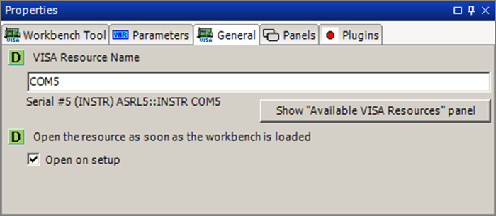
The OPC client creates an OPC device with the same name as the tool instance, to expose the configured OPC items as device entities, making it possible to map virtual device entities to OPC items.
The OPC Client tool can only be used as a workbench instance (it is not possible to create a new instance in a procedure step). That is necessary because the list of OPC items needs to be configured and setup before the tool methods can be used.
The tool supports ‘Simulate’ mode. By right clicking a workbench tool and selecting ‘Simulate’ in the menu the tool will simulate all OPC items. When using this mode it is possible to execute scripts without having access to the used OPC servers. The execution log will show that the used OPC items are in simulate mode and Get methods will just return the default value of the item.
This manual also contains a section on troubleshooting OPC problems.
Methods
Setup
Setup OPC Server connections and items.
The Setup method is used to setup the connection to the needed OPC Servers and the needed OPC Items. It is possible to setup a connection to any number of local and remote OPC Servers and any number of OPC Items.
The list of OPC Items will be presented to the script as a flat list where only the given name of each item is used, no matter which and how many different servers are used.
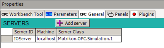
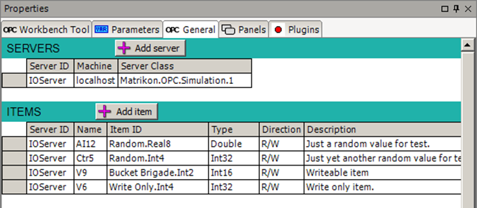
The list of servers is configured under the SERVERS section in the General tab of the properties.
A new server can be added by pressing the ‘Add server’ button of the SERVERS heading line.
An existing server connection can be removed by pressing the Delete key when the server line is selected.
A server connection can be moved up and down in the list by pressing Alt + Up or Alt + Down when the server line is selected.
There are three fields to setup for each connected OPC server:
- ServerIDThis is a text field where the user must set a descriptive short name for the server. This name is used in the item configurations to identify the parent server of each item.
- MachineNameThis is a text field for the name of the OPC server machine. It can be the machine name, the machine IP address or empty when connecting to a local OPC server.
Please note that this means that there is a difference between connecting to localhost (which involves DCOM) and connecting to the local OPC server by setting the MachineName to the empty string. Please see the section named Troubleshooting OPC problems for more.
- ServerClassThis is a text field for the class name of the OPC server on the specified machine. Click the browse-symbol (…) or press the space button to open a dialog for browsing available server classes on the selected machine.
The list of used OPC items is configured under the ITEMS section in the General tab of the properties.
A new item can be added by pressing the ‘Add item’ button of the ITEMS heading line or by pressing the Enter key on the line where you wish to insert a new item.
An existing item can be removed by pressing the Delete key when the item line is selected.
An item line can be moved up and down in the list by pressing Alt + Up or Alt + Down when the item line is selected.
The different fields for each item are:
- ServerIDThis is a text field where the parent server of the item is selected. The field must be set to the server ID of one of the servers configured in the servers list above.
- NameThis is a text field where the chosen name of the item is set. By default the name will be set to the name of the selected OPC item, but it can be set to a more descriptive name, making the scripts more readable and easy to maintain.
- ItemIDThis field is used to select the OPC item to use. Click the browse-symbol (…) or press the space button to open a dialog for browsing the server for available items.
- TypeThis field is for selecting the resulting data type of the item in SeqZap. The field will be set automatically when selecting the item via the item browser dialog.
- DirectionThis field shows the data access direction for the item; whether it is read-only, write-only or read-write.
- DescriptionThis is a text field where the item can be given a short description.
Error Handling in Setup
Many different errors can occur in the setup process. The different error types are listed below along with a description of how each error type is handled during setup.
Errors on server entries:
| Error description | In parser | Breaks setup |
|---|
Missing ‘Server ID’
The ‘Server ID’ field is empty. | Error | Yes |
Missing ‘Server Class’
The ‘Server Class’ field is empty. | Error | Yes |
Duplicate ‘Server ID’ on server entry
The ID has the same name as a pervious entry in the list. | Error | Yes |
The specified ‘Server Class’ was not found
The specified server class was not found on the specified machine. | No | No |
Errors on OPC items:
| Error description | In parser | Breaks setup | Step error | Simulates |
|---|
Missing ‘Server ID’
The ‘Server ID’ field is empty. | Error | Yes | Yes | No |
Unknown server ID
No server entry has the specified server ID. | Error | Yes | Yes | No |
Missing ‘Name’
The ‘Name’ field is empty. | Error | Yes | - | No |
Duplicate ‘Name’
The entry has the same name as a previous entry in the list. | Error | Yes | No | No |
Missing ‘Item ID’
The ‘Item ID’ field is empty. | Error | Yes | Yes | No |
Unknown item ID
The OPC server has no item with the specified ID. | Warning | No | Yes | No |
| Selected ‘Type’ is different from the data type of the item on the OPC server. | - | No | No | Yes |
| Selected ‘Direction’ is incompatible with the direction of the item on the OPC server. | - | No | No | Yes |
Syntax error in specified ‘Update Rate’
The specified update rate does not follow the supported format of a time interval value. | Error | Yes | No | No |
Quality is bad and not one of these values:
LastKnown, WaitingForInitialData | - | No | No | Yes |
The column ‘In Parser’ indicates whether the error is listed in the Errors and Warnings view, and whether it is reported as an error or as a warning.
The column ‘Breaks setup’ indicates whether the error will prevent the setup of the tool from completing. If the error breaks the setup, the error has to be fixed before the tool can be used.
The column ‘Step error’ indicates whether steps using the item will report an error in the Errors and Warnings view.
The ‘Simulates’ column indicates whether the error will force the tool into ‘Simulate’ mode.
Get Item Value
Gets the value for the specified OPC item.
This method gets the value of an OPC item.
The setup shows the list of available items for the selected OPC Client instance. The user can select one of the items on the list and the output data type of the procedure step will be set to the data type of the selected item.
Set Item Value
Sets the value for the specified OPC item.
This method sets the value of an OPC item.
The setup shows the list of available items for the selected OPC Client instance. The user can select one of the items on the list and the input data type of the procedure step will be set to the data type of the selected item.
Panels
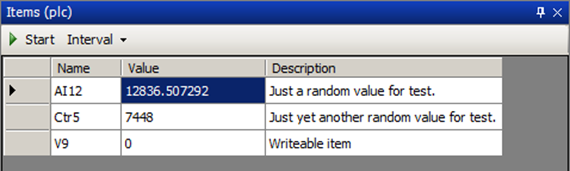
Items
Configured Items
The Items panel shows a table with the list of OPC items and their current values.
The values are automatically updated whenever the items are read, either in a test script or when items are periodically polled.
Polling can be started by pressing the Start button in the panel and the poll interval can be changed by clicking the Interval button and thereafter selecting an interval time in the drop-down menu that appears.
Using OPC items in a virtual device
The configured OPC items of an OPC Client tool can be used as sources by device entities of virtual devices. The virtual device entity types to use for OPC entities are the Simple Boolean, Simple Integer and Simple Decimal types.
Please refer to the Virtual Device Tool for more info on creating and using virtual devices.
Plugins
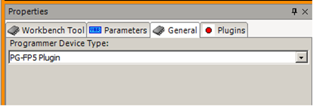
PG-FP5 Plugin
This plugin is a Programmer Plugin for the Programmer Tool and interfaces an NEC PG-FP5 flash programmer device through a COM-port or a USB port.
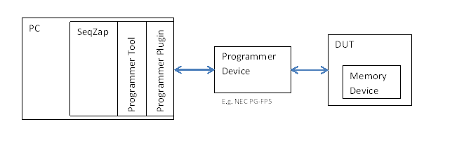
Please refer to the Programmer Tool manual for a description of how to use this plugin from SeqZap and how the plugin is used by the Programmer Tool.
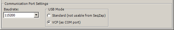
The physical connection to the FP5 can either be a standard RS232 COM port or the USB connector via a VCP-driver (Virtual Com Port). When the VCP-driver is used, the communication speed to the device is increased very much compared to the RS232 port speed. Please refer to the section about installation of the VCP-driver. The Status Panel of this plugin can be used to change the USB mode of the connected programmer from “Standard” to “VCP” mode.
The Programmer Device Object
Methods
The methods described below are the API methods of the plugin defined by the Programmer Tool and are used by the different Programmer Tool methods.
Setup
The Setup method has three parameters:
- PortWhich COM-port the PG-FP5 programmer device is connected to.
- ParametersFileA parameters file (*.pr5) to load into the PG-FP5 programmer device.
- SettingsFileA settings file (*.esf) to load into the PG-FP5 programmer device.
Four actions are performed in sequence:
- If setup has already been done, the
- Initialize
- Load parameters file
- Load settings file
Load
This method transfers a HEX-file with the memory image to the programmer device.
Erase
This method activates the Erase command on the device.
BlankCheck
This method activates the BlankCheck command on the device.
Program
This method activates the Programming command on the device. The PG-FP5 device can perform more than one action. Each action will report its progress, making it possible to see the progress of the command in the SeqZap UI.
Verify
This method activates the Verify command on the device. The PG-FP5 device can perform more than one action. Each action will report its progress, making it possible to see the progress of the command in the SeqZap UI.
CreateDevicePanelControl
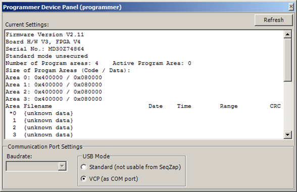
The device panel of the PG-FP5 plugin displays setup information and can also be used for changing baudrate and USB connection functionality of the programmer device.
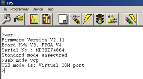
The Current Settings view is the output of the “conf” command. The output could be different in different versions of the programmer firmware.
The USB Mode selection controls whether the device USB port should connect to the PC as a standard driver or a VCP (Virtual Com Port) driver. SeqZap does not currently support the Standard mode.
When the USB VCP connection is used the Baudrate selection is disabled.
When using the RS232 port on the device the Baudrate selector will show the current baudrate.
Selecting another baudrate will send a baudrate change request (“brt” command) to the device. If the device responds successfully, the baudrate on the PC will be changed to the same baudrate and a new “brt” command is sent to the device to check whether the device is still responding.
Remember that this will not change the setup of the serial port tool. If the new baudrate should be used when the current script is loaded again, the baudrate also needs to be changed in the workbench.
Troubleshooting
Setup method reports “No response from programmer device”
When using the RS232 port on the device:
- Check that the cable is connected to both the PC and the programmer.
- Be sure to use a crossed cable (null-modem).
- Be sure to set the correct baud rate on the used serial port.
When using the USB connection via the VCP driver:
- The VCP driver from Renesas needs to be installed on the PC.
- A USB cable must be connected between the PC and the mini-USB connector on the programmer device.
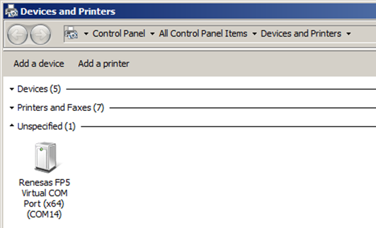
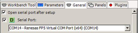
- Check that a “Renesas FP5 Virtual COM Port” is listed in the Devices and Printers view on the PC.
General:
- Check that the programmer device is switched on.
- Check that there is no error-message in programmer device display and that neither the BUSY LED nor the ERROR LED is lit or blinking.
- Try switching the programmer device off and then back on again.
Using the PG-FP5 USB VCP Driver
It is possible to speed up the communication between the PC and the programmer device by using USB and the special VCP driver for the FP5 programmer. By using the VCP driver the selected baud rate of the port will be ignored by the driver, and the communication will be done at USB-speed (measured to be more than 30 times faster than 115200 baud).
The VCP driver is not a part of the SeqZap installation.
Get more information and download the VCP driver from:
http://www.renesas.eu/
The latest firmware for the programmer device can be found at:
http://www2.renesas.eu/products/micro/download/index.html/?id=229
Changing to USB VCP mode
To change between using the RS232 port and the USB port you can follow one of the two procedures in the following sections.
Using the FP5 application from Renesas to switch to VCP mode
If you have the FP5 application from Renesas installed, you can use that application to switch to VCP mode. This procedure requires no RS232 connection, but only a USB cable.
Follow these steps:
- Install the Renasas FP5 VCP driver and restart PC if needed.
- Connect the USB cable between the FP5 programmer device and the PC.
- Open the Renesas FP5 application.
- Type the command: usb_mode vcp
- Press return
- Exit the FP5 application
- Switch off the programmer device and switch it back on again.
If the VCP mode has not been used before, the VCP driver will be installed for your programmer device.
The (virtual) COM port will be shown in your Windows device browser (Devices and Printers).
Using SeqZap to switch to VCP mode
You can use SeqZap to switch to VCP mode if you have an RS232 cable connection between the programmer device and the PC.
Follow these steps:
- Open SeqZap
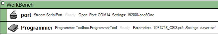
- Open or create a script file with a workbench with a serial port tool and a programmer tool. The serial port must be set to the current serial port and have the same settings for the serial port as the programmer device (e.g. baudrate). The programmer tool must be set to use the PG-FP5 plugin and the parameters must be setup.
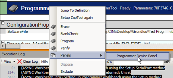
- Right click the programmer tool in the workbench to open the PG-FP5 plugin panel.
- Click the VCP radio button.
- Close the panel.
- Close SeqZap
- Connect the programmer to the PC with a USB cable.The RS232 cable can be removed.
- Switch off the programmer device and switch it back on again.If VCP mode has not been used on the PC before, the driver will be installed automatically for your device.
- Wait until the new virtual COM port is shown in the Windows device browser (Devices and Printers).
- Open SeqZap again and the script file.
- Change the setup of the serial port tool in the workbench to use the new virtual COM port.
- Right click the serial port tool in the workbench and select ‘Setup ZapTool’.
- Right click the programmer tool in the workbench and select ‘Setup ZapTool’.
SCPI Devices
The SCPI Devices plugin provides support for various GPIB/SCPI devices.
All devices use a standard SeqZap Stream for communicating with the device.
The SCPI Devices plugin is Connected Device plugin, a Connected Device Tool must be added to the workbench to setup the plugin and connected it to a GPIB device.
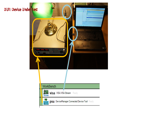
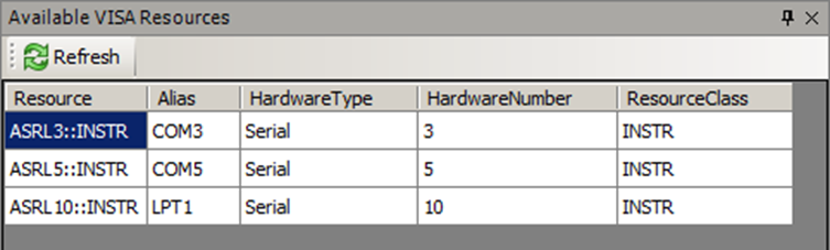
SCPI devices are usually connected to the PC by using a GPIB interface such as the National Instruments GPIB-to-USB interfaces supported by the NI VISA tool.
The figure above shows how a SCPI device workbench usually looks. The first workbench tool is a VISA resource using a National Instruments GPIB-to-USB device. The SCPI device is then setup as a Connected Device which use the VISA resource for transmitting GPIB commands. The lamp is the device under test (DUT).
SCPI AC Power Supply
Expose SCPI AC Power Supplies as AC Power Supply devices in the SeqZap device tree.
For instructions on how to use the SCPI power supply, please read the Power Supply section of this manual.
Supported Devices
Although most SCPI AC Power Supplies should work, SeqZap has been verified to work with the following list of power supplies:
- Chroma 6408
- Chroma 6430
- Chroma 61605
- Chroma 61704
If other power supplies are verified to work with SeqZap, please let CIM Software Testing know so the manual can be updated accordingly.
Setup
The only thing needed to setup a SCPI AC Power Supply is to set the stream to use in the Stream parameter.
Most GPIB interface devices are supported by the VISA Stream Tool.
Power Supply Toolbox
The Power Supply (PSU) toolbox defined an abstract interface to power supplies.
Power supplies are exposed as device entities in SeqZap, this means that they can be used in a virtual device.
The Power Supply toolbox does not provide any drivers to access power supplies, it only defines the PSU device entity and the methods to use a PSU in SeqZap scripts.
The power supply is represented as a device entity, but because the most power supplies needs some level of setup before they can be used, for example to configure the COM port to communicate over, the power supply is represented as a connected device plugin.
To use a connected device, a connected device tool must be added to the workbench:
The name of the connected device tool will also be the name of the device entity created.
In the General tab of the properties view, the specific connected device plugin to use can now be selected.
Some plugins require additional parameters to be set, the SCPI AC Power Supply plugin, for example, requires two parameters to be set. These parameters can both be set directly on the General tab or on the Parameters tab of the properties view.
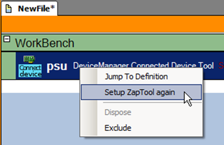
After the settings have been changed, the Power Supply must be setup again in the workbench.
Please remember that workbenches are parsed from top to bottom, so if the Power Supply requires another tool, for instance a serial port or VISA resource, that tool must be placed above the Power Supply tool in the workbench.
Items in a SeqZap script file are re-arranged by selecting the item and pressing Alt+Up/Down to move the item.
SeqZap includes an example script which use the Power Supply tool in the Examples\Tools\GPIB Power Supply directory where SeqZap is installed.
Additionally SeqZap also comes with the test projects which CIM Software Testing use to verify the Power Supply tool internally, the projects are located in the Test\SeqZapTest\Tools\PowerSupply direcotory.
In this directory the following tests are located:
- PSU_Verification: A sunshine test to verify the operation of a PSU, it is supposed to work with a physical PSU which supply a light-bulb.
- ScpiProtocolTest: Is a protocol test which use the Test Stream from the Stream tool to verify that SCPI commands sent by the AC SCPI Power Supply plugin.
- SystemTest: Automates SeqZap Studio to verify that the Power Supply tool can be added to a workbench and used from SeqZap scripts.
Access to AC power supplies.
The AC Power Supply defines a common set of methods that AC Power Supplies can be expected to support.
Many of the methods are only optional, and the method will report a parse error if the selected AC Power Supply device does not support the method.
All the methods can report InvalidOperationError if an AC Power Supply method is called in an invalid situation, for example if setting the voltage while the output is enabled is not allowed.
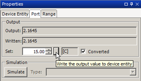
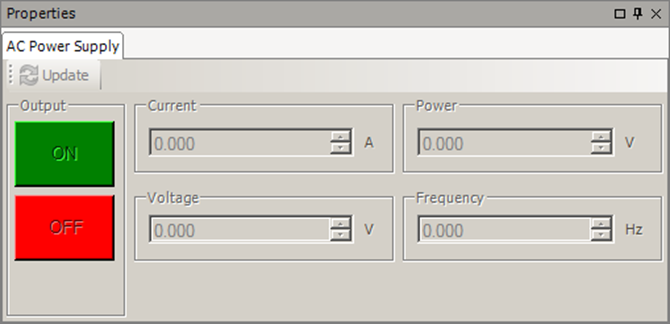
As most other device entities in SeqZap, the AC Power Supply entity also has a device entity panel.
The panel is shown by selecting a PSU entity in the device browser panel.
When the panel is initially shown it will refresh the state of the PSU, this is equivalent to pressing the Update button.
While the panel is updating the user-interface is disabled and cannot be used.
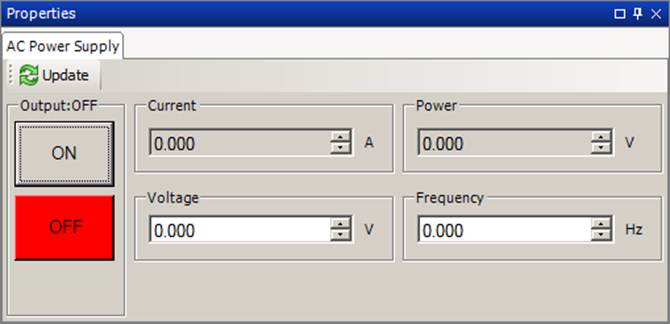
Figure 2 AC Power Supply entity in with output disabled
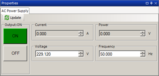
When the PSU is OFF (output is disabled) the Voltage value shows the configured voltage level – after the PSU is turned ON (output is enabled) the Voltage value shows the voltage level measured by the PSU.
Please note that the values shown in the panel is not updated automatically or refreshed periodically, to retrieve the current state of the power supply, the Update button must be pressed.
All the AC Power Supply methods take an AC Power Supply entity as the first argument, the power supply can both be a physical one or a virtual one mapped using the Virtual Device tool.
The AC Power Supply is described in detail earlier in this manual.
The OutputEnabled entity is a Simple Boolean Read/Write data entity, and can be used to enable the output on the power supply using generic Simple Boolean device methods.
Get the currently set AC RMS voltage in volts.
Get the output voltage (RMS) in volts.
This method is supported by all AC power supplies.
Set the output voltage (RMS) in volts.
This method is supported by all AC power supplies.
Get current as a decimal value measured in amperes (RMS).
This method is supported by all AC power supplies.
Enable the output of the power supply.
This method is supported by all AC power supplies.
Disable the output of the power supply.
This method is supported by all AC power supplies.
Determine whether the output of the power supply is enabled.
This method is supported by all AC power supplies.
Get a string which identifies the model and revision of the connected power supply.
This method is supported by all AC power supplies.
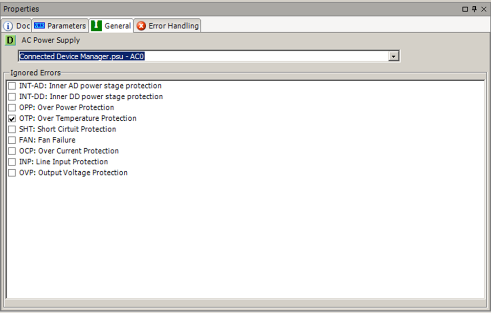
Ignore one or more errors that the AC Power Supply can report, this can be used to ignore errors which would otherwise result in a failed step.
This can, for example, be used to ignore a temporary “Over current protection” error which would otherwise cause the test to stop.
The ignored error will be ignored until the next call of the “Ignore Errors” method, un-ignoring all errors can be done by calling “Ignore Errors” without specifying any errors.
This method is supported by all AC power supplies.
Set the voltage range of the power supply.
If the range is not supplied, the power supply should automatically set the range.
Power supplies usually support a predefined set of ranges, e.g. 0-150 or 0-300, if the script tries to set an unsupported range InputOutOfRange is reported.
InputOutOfRange is also reported if the power supply does not support auto-range.
If the power supply does not support setting the voltage range a parsing error will be reported for the step.
Get the currently set frequency in Hz.
If the power supply does not support setting the voltage range a parsing error will be reported for the step.
Set the frequency in Hz.
If the power supply does not support the specified frequency, InputOutOfRange will be reported.
If the power supply does not support setting the voltage range a parsing error will be reported for the step.
Set the peak current limit on the power supply in amperes.
If the power supply does not support the specified current limit, InputOutOfRange will be reported.
If the power supply does not support setting the voltage range a parsing error will be reported for the step.
Get the power as a decimal value in watts.
If the power supply does not support setting the voltage range a parsing error will be reported for the step.
Get the power factor of the power supply.
If the power supply does not support setting the voltage range a parsing error will be reported for the step.
Get the crest factor of the power supply.
Get crest factor as a decimal value.
If the power supply does not support setting the voltage range a parsing error will be reported for the step.
Clear the latch protection of the power supply.
If the power supply does not support setting the voltage range a parsing error will be reported for the step.
Set the software overvoltage protection level of the ac source.
If the power supply does not support the given protection level, InputOutOfRange will be reported.
If the power supply does not support setting the voltage range a parsing error will be reported for the step.
Reset the power supply.
If the power supply does not support setting the voltage range a parsing error will be reported for the step.
Perform a self-test of the power supply.
If the self-test was not successful, SelfTestFailed is reported.
If the power supply does not support setting the voltage range a parsing error will be reported for the step.
Get a the list of errors which have been previously ignored.
A list of the errors which can be ignored is also returned as an array of strings.
Tools for related to programming of memory devices.
This toolbox contains tools related to the programming of memory devices.
Tool for programming memory devices.
This a general tool for erasing, programming and verification of general memory devices through a connected programmer device. Typical memory device types are flash-memory and EPROMs.
The Programmer Tool is a dynamic tool and the Setup method must be used on a new tool instance to select the kind of programmer device to use.
The ProgrammerTool uses a programmer plugin to interface a specific type of programmer device.
The relationship between SeqZap, the tool, the plugin and the programming device is illustrated below.
Setup the programmer tool.
This method initializes the programmer tool using the specified data.
The main parameter of this method is the programmer plugin selection, where the type of programmer is selected.
Depending on the selected programmer type (plugin), the Setup method will expand with any number of additional input parameters specified by the selected programmer plugin.
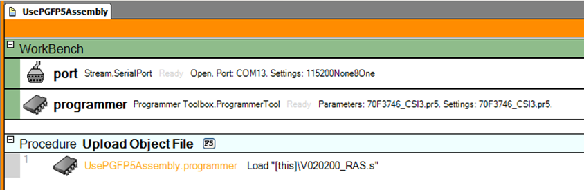
The example below shows a programmer tool instance created in a workbench.
Load the programmer memory.
This method loads a memory-data file into the programmer device, to prepare for Program and Verify actions.
The only parameter for this method is the file path to the HEX-file to load.
Erase the device memory.
This method erases the memory device to prepare it for a new programming.
The method has no parameters.
Blank Check the device memory.
This method reads the complete memory device to check whether it is totally ‘blank’ (all memory is in its initial cleared state).
The method has no parameters.
Program the device memory.
This method programs the memory device using the file loaded with the Load method.
The method has no parameters.
Verify the programmed device memory.
This method reads the complete memory device and checks whether all memory addresses have the same value as specified in the loaded file.
The method has no parameters.
Erase, BlankCheck, Program and Verify the device memory.
This is a convenience method that sequentially performs the commands:
- Erase,
- Blank Check,
- Program and
- Verify.
If any of the commands fails, the subsequent commands are not performed.
The method has no parameters.
Gets the latest updated state of the programmer device (plugin).
This is a read-only text property that returns a string with the current state of the selected device plugin. The string has no specific format. The developer of the programmer plugin chooses the information it contains.
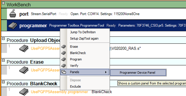
Shows a custom panel from the selected programmer plugin.
The panel is opened by right-clicking the workbench tool and selecting Panels → Programmer Device Panel.
The panel will contain a device specific panel from the selected Programmed Device Plugin.
The example shown below is the panel for the PG-FP5 programmer plugin.
The programmer device API defines the interfaces to use when implementing programmer device plugins.
The API is only relevant for software developers implementing a plugin for a specific programmer device type.
This section will not describe all the details of the API, but will describe the purpose and usage of the defined interfaces, methods, properties and events. Please refer to the Programmer Tool assembly for the latest build-in documentation.
This defines the interface of a programmer plugin. The interface has only a few methods.
Methods
This must return the list of additional plugin specific parameters for the Setup method of the programmer tool. The parameters specified by this method will be passed to the Setup method of the programmer device object.
This method is used to create a programmer device object (implements the IProgramerDevice interface) to be used by the programmer tool instance to perform all programming actions.
Programmer device objects must implement the IProgrammerDevice interface defined by the Programmer Tool assembly. The interface defines the methods, properties and events the Programmer Tool will use to perform the programming actions.
This method is called by the Setup method of the Programmer Tool instance to initialize and setup the programmer device. After this method has been called, the device should at least be ready for the Erase and Blank Check operations.
The Programmer tool instance will pass the arguments (values) of the parameters that were specified by the IProgrammerPlugin.ListSetupParameters method.
This method is used to transfer the memory image file to the programmer device or the programmer device object.
After this method has been called, the programmer device should be ready for Program and Verify commands.
This method is used to perform an Erase operation with the programmer device.
This method is used to perform a Blank Check operation with the programmer device.
This method is used to perform a Program operation with the programmer device.
This method is used to perform a Verify operation with the programmer device.
This method creates a UI control for user interaction with the programmer device. The functionality and look of the control is specific for each programmer plugin.
This read-only property returns an object to be used for locking (reserving) the programmer device object while performing one or more operations.
This is a read-only property returning a textual single line description of the state of the programmer device.
This event notifies when the State property text has changed.
SampleArray
Tools for sampled data.
Used by other tools to view, measure, generate and analyze multi-channel sample-data
The Sample Array tool is a data tool and is used for holding multi-channel constant samplerate or timestamped samples.
An instance of a Sample Array
SampleArray
Methods
Create SampleArray Data
Creates some sample array data. The data can either be the same value or generated by a signal generator.
Create SampleArray
Creates a sample array. The data can either be 0s (zeroes) or generated by a signal generator.
Create SampleArray with iregular sample timing.
Creates a sample array with the specified channels and with no samples.
Get Length
Get the length of the sample array (number of samples on each channel).
Get Sample Count
Get the number of samples on the specified channel.
Add sample to specified channel.
Adds a single sample to the specified channel.
Set Sample Value
Set the value of a single sample on the specified channel at the specified index. SampleArray must not be read-only.
Get Sample Value and Time
Get the value of a single sample on the specified channel at the specified index.
Clone SampleArray
Makes a clone of the SampleArray.
Add Value
Adds the specified value to every sample in the SampleAray.
Multiply
Multiplies every sample in the SampleAray with the specified value.
Rotate SampleArray
Rotate the samples in the SampleArray in the specified direction.
Get Statistics
Get statistic information about the samples.
Diff
Calculate the difference between two sample arrays and return it as a new sample array
CompareChannelWithReference
Compare a channel and the specified reference curve by finding the maximum deviation.
The TimeDeviation field is used to set the timing tolerance of the comparison. If the TimingTolerance is set to zero, all samples are compared one-to-one with the reference. If TimingTolerance is set to 2, every sample is compared to 5 samples (2 before and 2 after) in the reference (e.g. sample 6 is compared to reference samples 4,5,6,7 and 8). The smallest deviation of the 5 is used.
The WrapEnds field can be used for cyclic data. When TimeDeviation is set to 1, sample 0 of the array will also be compared to the last sample of the reference SampleArray.
Set Current Inspection Mark
Sets current point for inspection of the data.
Set Logic Levels
Sets the HI and LO levels for converting to logic level.
Convert To Logic Changes
Gets the sample number and time for the next change in logic level.
Get Next Logic Level Change
Gets the sample number and time for the next change in logic level.
Get Channel Trig Point
Get the time where the samples of a channel crosses the specified value.
Save CSV file
Save sample array as a CSV file.
Save CSV file interactively
Load CSV File
Load sample array from a CSV file.
Properties
ReadOnly
Channels
Samples
MaxLength
Panels
Sample Arrays
Investigate the created sample arrays
Stream
General stream handling toolbox.
The stream toolbox provides access to a lot of stream oriented devices, such as serial ports, files and network connections.
Many SeqZap tools utilize the stream toolbox to define a protocol which can work any underlying stream, the same protocol will work for both serial ports and network connections, for instance.
Included Examples
Stream
Data stream
This is the base on which all other streams are based, so everything defined on the stream is also defined on the other streams.
Methods
Open
Open the stream
Open the stream.
Close
Close the stream
Close the stream.
Read String
Read a string from a stream
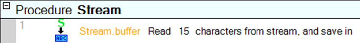
Read a number of characters from the stream.
Read Line
Read a line from a steam.
Read a line of data from a stream as a string.
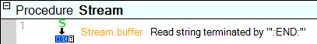
The line terminator can be changed on the setup page.
Read Byte
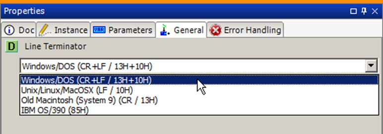
Read a single byte from a steam.
Read a single byte from a stream.
The byte is returned both as the actual value, and as a single character as defined by stream’s encoding.
Read Until
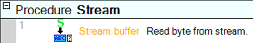
Read from a stream until a given string is read.
Read from the stream until the given terminator is read.
Read Until Silent
Read from a steam until no data has been received for a given time.
Read from a stream until it has been silent for a defined time.
Write String
Write a string to the stream
Write a string to the stream using the encoding defined on the stream.
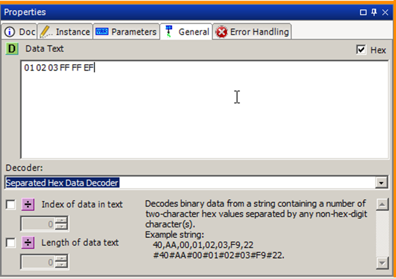
Write Binary Data from string
Write binary data to the stream. The data is taken from a string listing the binary values. To decode the data string a decoder for the specific format must be selected.
Write binary data to the stream.
The binary data is given as a hexadecimal encoded string.
Write Text
Write multiple lines of text to the stream
This method has been deprecated.
Flush
Flush read/write buffers of the stream
Flush the buffers of the stream.
Read XML
Read an XML element from the stream.
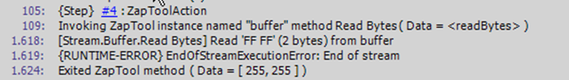
Read Bytes
Read a number of bytes from the stream
Read a given number of bytes from the stream.
If the stream reports an error while reading (timeout or end-of-stream), the script can ignore this error using the Error Handling tab and the bytes which was read will still be returned.
Write Bytes
Write an array of bytes to the stream
Write an array of bytes to a stream.
The bytes are given as an array of integers, if the integers given is outside the range of byte the ValueOutOfRangeError will be reported.
Request and wait for response
Write a string or byte-array to a stream and read the response.
Write a string or an array of bytes and wait for, and read the response.
This method is useful because other users of the stream are prevented from using the stream while the Request and wait for response step is executing, for example to prevent panels from reading and writing from the stream while waiting for a response.
The input and output data are always the same type, so the step should be marked as either using strings or a byte array.
Properties
WriteTimeout
ReadTimeout
IsOpen
DataAvailable
The number of bytes available for reading on the stream.
SupportsDataReceived
Panels
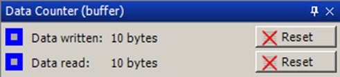
Data Counter
Provides a byte counter to observe how many bytes are read/written
The data counter provides an easy way to monitor whether data is being read and/or written from/to a stream.
The reset button will reset that counter to 0.
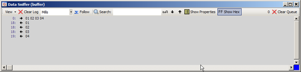
Data Sniffer
Sniff the read/write data of a stream.
The data sniffer panel is used to monitor the bytes passing through the stream.
It uses the same functionality for clearing/following and searching as the execution log in SeqZap.
The data sniffer can also show the transferred bytes as hexadecimal values by toggling the “Show Hex” button.
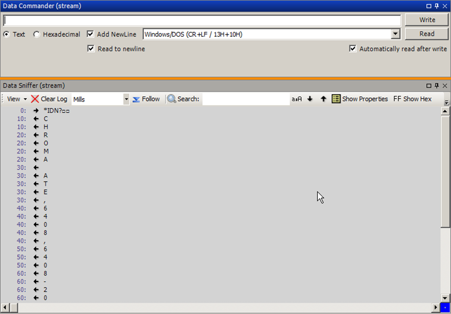
Data Commander
Write directly to a stream.
The Data Commander panel is used to write to a stream, or tell the stream to read.
The panel does not show the data written or read, so it is normally paired with the Data Sniffer panel.
Figure 3 Data Commander docked above Data Sniffer
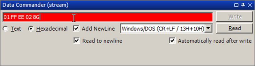
The Data Commander can both transmit textual data (encoded using the streams text encoding, UTF-8 by default), or hexadecimal byte data by selecting the relevant option button.
When enter/return is pressed in the input field or the “Write” button is pressed, the data is written to the stream, optionally followed by a newline character if the “Add NewLine” box is checked.
If the “Automatically read after write” box is checked, the Data Commander will read the available data from the stream, or up until a newline character if the “Read to newline” box is checked.
The same read operation is performed if the “Read” button is pressed.
When sending hexadecimal data, the input field will turn red if the input is not valid hexadecimal data:
In addition, the “Write” button is disabled.
Errors
All read/write tool methods in the stream tool can report the following errors back.
TimeoutExecutionError
StreamNotOpenExecutionError
Reported when trying to read/write to a stream that is not yet open.
OperationNotSupportedError
If you try to write to a stream that does not support writing (e.g. a file opened in read mode) - or reading from a stream that does not support reading.
SerialPort
Physical port
Please see Stream tool for information about the methods, properties and panels on the Serial Port.
SeqZap includes an example use of the serial port.
Methods
Open
Close
Read String
Read a string from a stream
Read Line
Read a line from a steam.
Read Byte
Read a single byte from a steam.
Read Until
Read from a stream until a given string is read.
Read Until Silent
Read from a steam until no data has been received for a given time.
Write String
Write a string to the stream
Write Binary Data from string
Write binary data to the stream. The data is taken from a string listing the binary values. To decode the data string a decoder for the specific format must be selected.
Write Text
Write multiple lines of text to the stream
Flush
Flush read/write buffers of the stream
Setup SerialPort
Setup a serial port and set baud rate, parity, etc.
Open SerialPort
Open a serial port and setup baud rate, parity, etc.
Read XML
Read an XML element from the stream.
Read Bytes
Write Bytes
Request and wait for response
Properties
ReceiveError
Indicates whether a receive error has been detected.
LastReceiveError
Gets the value of the last receive error.
Parity
Get the parity of the open serial port.
Handshake
Get the handshake of the open serial port.
BaudRate
Get the baud-rate of the open serial port.
DataBits
Get the number of data-bits of the open serial port.
StopBits
Get the number of stop-bits of the open serial port.
DataAvailable
CtsHolding
Gets the state of the Clear-to-Send line.
DsrHolding
Gets the state of the Data Set Ready signal.
DtrEnable
Gets or sets a value that enables the Data Terminal Ready (DTR) signal during serial communication.
RtsEnable
Gets or sets a value indicating whether the Request to Send (RTS) signal is enabled during serial communication.
CDHolding
Gets the state of the Carrier Detect line for the port.
WriteTimeout
ReadTimeout
IsOpen
SupportsDataReceived
Panels
Data Counter
Provides a byte counter to observe how many bytes are read/written
Data Sniffer
Sniff the read/write data of a stream.
Data Commander
FileStream
Read/Write from a file on a filesystem.
Methods
Open
Close
Read String
Read a string from a stream
Read Line
Read a line from a steam.
Read Byte
Read a single byte from a steam.
Read Until
Read from a stream until a given string is read.
Read Until Silent
Read from a steam until no data has been received for a given time.
Write String
Write a string to the stream
Write Binary Data from string
Write binary data to the stream. The data is taken from a string listing the binary values. To decode the data string a decoder for the specific format must be selected.
Write Text
Write multiple lines of text to the stream
Flush
Flush read/write buffers of the stream
Open File
Open a file for reading or writing.
Read XML
Read an XML element from the stream.
Read Bytes
Write Bytes
Request and wait for response
Panels
Data Counter
Provides a byte counter to observe how many bytes are read/written
Data Sniffer
Sniff the read/write data of a stream.
Data Commander
Properties
WriteTimeout
ReadTimeout
IsOpen
DataAvailable
SupportsDataReceived
StringStream
Read from a string and write to a string.
Methods
Open
Close
Read String
Read a string from a stream
Read Line
Read a line from a steam.
Read Byte
Read a single byte from a steam.
Read Until
Read from a stream until a given string is read.
Read Until Silent
Read from a steam until no data has been received for a given time.
Write String
Write a string to the stream
Write Binary Data from string
Write binary data to the stream. The data is taken from a string listing the binary values. To decode the data string a decoder for the specific format must be selected.
Write Text
Write multiple lines of text to the stream
Flush
Flush read/write buffers of the stream
Open String
Read XML
Read an XML element from the stream.
Read Bytes
Write Bytes
Request and wait for response
Panels
Data Counter
Provides a byte counter to observe how many bytes are read/written
Data Sniffer
Sniff the read/write data of a stream.
Data Commander
Properties
WriteTimeout
ReadTimeout
IsOpen
DataAvailable
SupportsDataReceived
Buffer
Provides a writeable stream that buffers the written data until it is read.
Methods
Open
Close
Read String
Read a string from a stream
Read Line
Read a line from a steam.
Read Byte
Read a single byte from a steam.
Read Until
Read from a stream until a given string is read.
Read Until Silent
Read from a steam until no data has been received for a given time.
Write String
Write a string to the stream
Write Binary Data from string
Write binary data to the stream. The data is taken from a string listing the binary values. To decode the data string a decoder for the specific format must be selected.
Write Text
Write multiple lines of text to the stream
Flush
Flush read/write buffers of the stream
Read XML
Read an XML element from the stream.
Read Bytes
Write Bytes
Request and wait for response
Panels
Data Counter
Provides a byte counter to observe how many bytes are read/written
Data Sniffer
Sniff the read/write data of a stream.
Data Commander
Properties
WriteTimeout
ReadTimeout
IsOpen
DataAvailable
SupportsDataReceived
TCP Connection
TCP Connection to a remote server
Methods
Open
Close
Read String
Read a string from a stream
Read Line
Read a line from a steam.
Read Byte
Read a single byte from a steam.
Read Until
Read from a stream until a given string is read.
Read Until Silent
Read from a steam until no data has been received for a given time.
Write String
Write a string to the stream
Write Binary Data from string
Write binary data to the stream. The data is taken from a string listing the binary values. To decode the data string a decoder for the specific format must be selected.
Write Text
Write multiple lines of text to the stream
Flush
Flush read/write buffers of the stream
Open TCP Stream
Open a TCP connection to a remote server.
Read XML
Read an XML element from the stream.
Read Bytes
Write Bytes
Request and wait for response
Properties
NoDelay
WriteTimeout
ReadTimeout
IsOpen
DataAvailable
SupportsDataReceived
Panels
Data Counter
Provides a byte counter to observe how many bytes are read/written
Data Sniffer
Sniff the read/write data of a stream.
Data Commander
UDP Connection
One-to-one UDP connection (listens on a UDP port).
Methods
Open
Close
Read String
Read a string from a stream
Read Line
Read a line from a steam.
Read Byte
Read a single byte from a steam.
Read Until
Read from a stream until a given string is read.
Read Until Silent
Read from a steam until no data has been received for a given time.
Write String
Write a string to the stream
Write Binary Data from string
Write binary data to the stream. The data is taken from a string listing the binary values. To decode the data string a decoder for the specific format must be selected.
Write Text
Write multiple lines of text to the stream
Flush
Flush read/write buffers of the stream
Open TCP Stream
Start listening on a UDP port, and set the destination for data written to this stream.
Write string to UDP receiver
Write a string to a receiver the stream
Read XML
Read an XML element from the stream.
Read Bytes
Write Bytes
Request and wait for response
Properties
ListenPort
WriteTimeout
ReadTimeout
IsOpen
DataAvailable
SupportsDataReceived
Panels
Data Counter
Provides a byte counter to observe how many bytes are read/written
Data Sniffer
Sniff the read/write data of a stream.
Data Commander
Telnet Connection
Telnet Connection to a remote host
Methods
Open
Close
Read String
Read a string from a stream
Read Line
Read a line from a steam.
Read Byte
Read a single byte from a steam.
Read Until
Read from a stream until a given string is read.
Read Until Silent
Read from a steam until no data has been received for a given time.
Write String
Write a string to the stream
Write Binary Data from string
Write binary data to the stream. The data is taken from a string listing the binary values. To decode the data string a decoder for the specific format must be selected.
Write Text
Write multiple lines of text to the stream
Flush
Flush read/write buffers of the stream
Open Telnet Stream
Open a telnet connection to a remote host.
Read XML
Read an XML element from the stream.
Read Bytes
Write Bytes
Request and wait for response
Panels
Data Counter
Provides a byte counter to observe how many bytes are read/written
Data Sniffer
Sniff the read/write data of a stream.
Telnet Options
Lists the negotiated options for a telnet connection.
Telnet Values
Lists values used and negotiated for the telnet connection.
Data Commander
Properties
WriteTimeout
ReadTimeout
IsOpen
DataAvailable
SupportsDataReceived
Null
A write-only stream that discards all data written to it.
Methods
Open
Close
Read String
Read a string from a stream
Read Line
Read a line from a steam.
Read Byte
Read a single byte from a steam.
Read Until
Read from a stream until a given string is read.
Read Until Silent
Read from a steam until no data has been received for a given time.
Write String
Write a string to the stream
Write Binary Data from string
Write binary data to the stream. The data is taken from a string listing the binary values. To decode the data string a decoder for the specific format must be selected.
Write Text
Write multiple lines of text to the stream
Flush
Flush read/write buffers of the stream
Read XML
Read an XML element from the stream.
Read Bytes
Write Bytes
Request and wait for response
Panels
Data Counter
Provides a byte counter to observe how many bytes are read/written
Data Sniffer
Sniff the read/write data of a stream.
Data Commander
Properties
WriteTimeout
ReadTimeout
IsOpen
DataAvailable
SupportsDataReceived
TCP Server
Listen for TCP incoming connections
Methods
Open TCP Server
Start listenining for TCP connections from clients.
Accept
Accept a client connection
Close
Properties
Pending
True if there are any connections waiting to be handled.
AcceptedClients
The number of clients that have been served using Accept()
IsListening
True if the server is currently listening on the socket
Port
The port on which the server is listening
DotNetStream
Read/Write from standard dot net stream.
Methods
Open
Close
Read String
Read a string from a stream
Read Line
Read a line from a steam.
Read Byte
Read a single byte from a steam.
Read Until
Read from a stream until a given string is read.
Read Until Silent
Read from a steam until no data has been received for a given time.
Write String
Write a string to the stream
Write Binary Data from string
Write binary data to the stream. The data is taken from a string listing the binary values. To decode the data string a decoder for the specific format must be selected.
Write Text
Write multiple lines of text to the stream
Flush
Flush read/write buffers of the stream
Read XML
Read an XML element from the stream.
Read Bytes
Write Bytes
Request and wait for response
Panels
Data Counter
Provides a byte counter to observe how many bytes are read/written
Data Sniffer
Sniff the read/write data of a stream.
Data Commander
Properties
WriteTimeout
ReadTimeout
IsOpen
DataAvailable
SupportsDataReceived
TestStream
Stream for testing protocol ZapTools.
Methods
Open
Close
Read String
Read a string from a stream
Read Line
Read a line from a steam.
Read Byte
Read a single byte from a steam.
Read Until
Read from a stream until a given string is read.
Read Until Silent
Read from a steam until no data has been received for a given time.
Write String
Write a string to the stream
Write Binary Data from string
Write binary data to the stream. The data is taken from a string listing the binary values. To decode the data string a decoder for the specific format must be selected.
Write Text
Write multiple lines of text to the stream
Flush
Flush read/write buffers of the stream
Setup TestStream
Set Auto Response
. To decode the data string a decoder for the specific format must be selected.
Read XML
Read an XML element from the stream.
Read Bytes
Write Bytes
Clear Auto Response
Request and wait for response
Properties
SourceStream
The source stream to use in PassThrough mode, and to use if test data should be verified against the real target.
Mode
PassThrough
The mode of the stream. If set to true, the stream will pass dta in both directions to the source stream.
WriteTimeout
ReadTimeout
IsOpen
DataAvailable
SupportsDataReceived
Panels
Data Counter
Provides a byte counter to observe how many bytes are read/written
Data Sniffer
Sniff the read/write data of a stream.
Data Commander
ConnectedPairStream
Read from a string and write to a string.
Methods
Open
Close
Read String
Read a string from a stream
Read Line
Read a line from a steam.
Read Byte
Read a single byte from a steam.
Read Until
Read from a stream until a given string is read.
Read Until Silent
Read from a steam until no data has been received for a given time.
Write String
Write a string to the stream
Write Binary Data from string
Write binary data to the stream. The data is taken from a string listing the binary values. To decode the data string a decoder for the specific format must be selected.
Write Text
Write multiple lines of text to the stream
Flush
Flush read/write buffers of the stream
Setup ConnectedPair stream
Read XML
Read an XML element from the stream.
Read Bytes
Write Bytes
Request and wait for response
Panels
Data Counter
Provides a byte counter to observe how many bytes are read/written
Data Sniffer
Sniff the read/write data of a stream.
Data Commander
Properties
WriteTimeout
ReadTimeout
IsOpen
DataAvailable
SupportsDataReceived
Allows automation of WebDriver targets (web-browsers and mobile phones) using the WebDriver/Selenium driver.
The WebDriver Toolbox acts as a link between SeqZap’s general user interface testing tool, the Windows Automation Tool, and the WebDriver supported by all the major browser vendors such as Google Chrome, Mozilla Firefox and Microsoft Edge.
The WebDriver tool instance will setup the specific WebDriver target to test against: a web browser or a mobile phone.
It also provides non user interface methods for things specific to WebDriver which are not supported by the Windows Automation Tool, such as navigating to an URL or reloading the page.
Because the WebDriver tool is also a Remote Windows Automation Tool, it is always used with an instance of the Windows Automation Tool which then references the WebDriver Tool.
The WebDriver tool can run tests on any of the supported browsers, which currently are:
- Google Chrome
- Mozilla Firefox
- Microsoft Edge
- Microsoft Internet Explorer
When writing scripts, however, Google Chrome is the only supported browser since we provide special handling for that browser to make it possible to select the element to interact with using the mouse and the browser.
It is a good idea to first understand how the Windows Automation Tool works by reading the introduction for that tool.
Writing WebDriver tests uses the same way of writing tests, that is, by selecting the element to click by dragging the mouse over the element and using the element selection dialog to define a good selector for that element.
We really recommend using two screens when writing WebDriver tests so that one screen can show SeqZap, and the other can show the browser.
IFrames require special handling when writing and running a test, instructions for how to do this is described in the section of the manual for the IFrames panel.
Create new WebDriver instance.
This allows selecting the browser to use.
It also contains the list of HTML attributes to show for each element, this list is given as an input parameter to the Setup method.
If the web application under test requires special attributes to be available during test, they can be added to the list at Setup, for instance, to support one of the application specific data-* attributes.
By default the following list of attributes are:
- id
- class
- name
- placeholder
- href
- data-id
Navigate to a webpage identified by an url.
Navigate backwards in the browser.
Navigate forward in the browser.
Refresh the currently loaded webpage.
Execute a script (JavaScript) command on the running driver (browser).
Future WebDriver calls are directed to the selected IFrame.
Exit the IFrame most recently entered using the Enter IFrame method.
The title of the current page.
The url of the current page.
PageSource
The source of the current page.
The version of the browser.
If true (the default), selectors which use the "e;Value"e; property ignore the character casing of the Value to compare.
The IFrames panel is used to navigate and test web applications which use IFrames.
The IFrames panel lists all the IFrames on the current page, refreshed every second.
When the mouse cursor is above an IFrame in the list, the rectangle of that IFrame will be highlighted in the browser if available.
This can be illustrated by navigating to a page with IFrames, for example, the Theme Preview page on wordpress.org.
The list of IFrames is shown in the IFrames panels.
If the mouse hovers the first IFrame, which is the preview of the selected theme:
Then that IFrame will be highlighted in the browser:
This can be used to inspect the IFrames of a page.
The panel can also be used when writing the test, by right clicking an IFrame, it is possible to either Enter the IFrame right now – as part of writing a test script or just for debugging, or to Copy a step to enter the IFrame to the clipboard, which can than later be pasted in a test script.
It is a useful exercise when writing a test script, to use the “Enter IFrame” menu item, and watch the Element Spy panel change when an IFrame is entered.
IFrames are handled differently when testing a web-application, because each IFrame is a separate HTML document / tree. This means that the element tree follows the current IFrame (or the top page) and changes when an IFrame is “entered” in a test script.
This can be observed when a test script for the previously shown “Wordpress Theme Preview” page is under test.
If we try to select the “Theme Preview” headline of the preview, only the IFrame can be selected.
But if the preview IFrame is entered:
Then it becomes possible to select the Theme Preview headline:
To exit the IFrame again, the “Exit IFrame” method should be used, either in the test script or, while writing the test script, by calling the method from the workbench:
The Windows Automation toolbox is SeqZap’s standard way of automating any user interface element.
The Windows Automation toolbox provides a standardized view of any user interface, both locally running windows applications as well as remotely running user interfaces running on an embedded target or another PC.
The Windows Automation toolbox allows any user interface to be automated, is just requires a remote connection to be implemented for that particular user interface (UI) technology.
Using this approach, browsers and mobile phones can be automated just as easily as a locally running windows application such as Word.
Methods used to automate Windows (Win32, Windows.Forms, WPF, etc.) applications.
The element spy shows the local elements on the machine where SeqZap is running.
It can be used to determine whether a particular element on the screen can be seen by SeqZap, and what values and actions are available for that element.
When an element in the tree is selected it will detailed information about that element.
Please note that while one SeqZap process is never visible to itself it is, however, possible to see one SeqZap process from another SeqZap process.
If the mouse cursor hovers over an element and that element is currently shown on the screen, then that element is marked with a magenta overlay.
In the screenshot above the mouse cursor is pointing at the “Ribbon” part of the running Word application.
This panel is static and therefore available directly from the Panels->ZapTool Panels menu inside SeqZap, but the panel also comes in an instance bound variant.
Makes it easier to write windows automation scripts
Most user interface (UI) technologies arrange their UI elements, such as buttons, textboxes and dialogs in a tree. By navigating this tree, the user interface of an application can be reduced to a logical view rather than just the raw bitmap/pixal data which makes up a screenshot.
In the example above, an example “save dialog” is deconstructed into the separate entities that make up the entire dialog. Each element in the user interface can have much information associated with it, such as:
- AutomationId, for instance, the OK button may have the AutomationId “overwriteOkButton”.
- Value, for instance, “OK” for the OK button.
- ControlType, the buttons are marked as buttons, the text label is marked as a label, and so on.
All these bits of information are referred to as identifiers in the Windows Automation tool, because they are used to identify elements in the user interface, for instance, to identify the button to click.
For instance, in the example above we could use Value = ‘OK’ to identify the OK button.
When writing a user interface test using the Windows Automation Tool, the element to interact with – for instance the element to click – must be identified in the script.
To identify user interface elements, selectors are used to describe the path that the Windows Automation tool must take to navigate the user interface tree to the element to interact with.
Selectors are lists of identifiers along with an expected value, for instance: Value = ‘OK’ is an identifier (Value) with an expected value (OK).
In the “Save dialog” example above, the selector to identify the OK button would have to have three selector parts:
- One identifying the dialog
- One identifying the content part of the dialog
- And one identifying the OK button.
In reality, selectors are usually deeper, depending on the complexity of the user interface under test, but for this simple example a selector for the OK button could be:
- AutomationId = ‘OverwriteDialog’
- AutomationId = ‘Content’
- Value = ‘OK’
Sometimes parts of the path to an element cannot be described in a way which makes the test robust enough, for instance a selector containing AutomationId = 312131 looks like something which is generated dynamically by the application, and something which will change the next time the application is run.
In this case it is possible to simply just put a wildcard * (star) on that position of the selector. In the example above, we could ignore the content element, by using this selector instead:
- AutomationId = ‘OverwriteDialog’
- *
- Value = ‘OK’
This will make the Windows Automation tool try to search all elements at that level in the tree for a child where the Value = ‘OK’ identifier matches.
Furthermore, it is possible to ignore several levels of elements in the user interface tree by using the ** (double star) wildcard – this wildcard is referred to as the “all descendants” wildcard. For instance:
This will make the Windows Automation tool search for any element where the Value = ‘OK’ identifier matches, no matter where it is in the tree.
Wildcards can be combined and used multiple times to create short paths for very complex user interface trees, for instance:
- **
- AutomationId = ‘ScriptEditor’
- **
- Value = ‘Edit’
This selector will first find any elements matching AutomationId = ‘ScriptEditor’ in the user interface tree, and then from each of those elements, look for any element which matches the Value = ‘Edit’ identifier.
By default, the Windows Automation tool will search the entire tree to make sure that only one element matches the entire selector, this is done to make sure that the Windows Automation tool will not accidentally interact with an unwanted element.
All Windows Automation tool steps/methods which interacts with an element needs to have the selector for that element defined.
In the example above, a “Click” step for clicking the Windows start button has been inserted.
It is, of course, possible to change the selector manually using the “Add/Remove/Up/Down” buttons and the keyboard, but it is much easier to use the “Select (push and drag)” and “Select (in 5 seconds)” buttons shown above the selector.
Both buttons will change the selector to reflect the element under the mouse button, but work in two different ways:
- Select (push and drag) – here the element is selected by pressing and holding the left mouse button down on the button, and then dragging the mouse to the element which the selector should refer to and then releasing the left mouse button.
- Select (in 5 seconds) – can be used to click elements which hide themselves when another application is clicked – for instance to click a sub menu-item. So the element is selected by clicking the button, and then, within 5 seconds, moving the mouse to element which the selector should refer to. 5 seconds should be enough to open any menu items to point to a sub menu-item.
It is easier to try this than to read about it, so experimenting is usually a good way to get acquainted with the Windows Automation Tool’s selector.
In both cases the element under the mouse is highlighted using a transparent magenta rectangle.
When the “Use selector dialog” button is active/highlighted (by default it is), then the Element Selection Dialog is shown after an element is selected.
Using this dialog, the script writer can improve on the selector which the Windows Automation Tool can find to the highlighted element.
The Element Selection Dialog will examine the user interface tree to find the identifiers of the elements, and list the identifiers which results in a unique selector.
In the screenshot above, the Element Selection Dialog is showing the possible selectors which point to the “File Explorer” icon on the Windows start menu.
The script writer can then look at the individual elements in the selector and select the relevant identifier to use, the script writer can also choose to use the * wildcard to ignore parts of the selector.
After the Element Selection Dialog has found the possible identifiers for each of the element selector elements, it will try to find even shorter selectors using the ** (all descendants) wildcard. If any wildcard selectors are found, they will be shown in a new list in the dialog.
In the screenshot above, the Element Selection Dialog has found a very short selector which uniquely identifies the element, the script can use this step:
Instead of this step:
Using the shorter selector has the potential of making the test more robust against changes to the user interface, for instance, if a button is moved in the user interface tree. But the Element Selection Dialog can only help to suggest unique identifiers to an element, only the script writer can tell whether a selector is good or bad using knowledge about the application under test.
This section of the manual explains various strategies for testing various user interface elements.
A table does not normally have individual identifiers on each cell of the table to be used when automating the table.
This means that it might be hard to find a way to identify the particular cell to use in a test.
Consider the following table:
| Name | Value |
|---|
| Parameter A | 312.32 |
| Parameter B | 12.3 |
| Parameter C | -123 |
For a human, it is easy to see that by using the parameter name, it is easy to find the value of that particular parameter by looking in the same row in the table.
We can use this when identifying the value cell of a particular row in the table.
Instead of trying to identify the value cell using the Element Selection Dialog a good strategy is to use the Element Selection Dialog to identify the name cell for that particular cell. For instance:
** / InnerText = “Parameter A”
We can then use the .. selector to navigate to the parent of the name cell, the row, and then navigate to cell two, which is identified as child 1 of the row (the first child has index 0).
** / InnerText = “Parameter A” / .. / 1
In this way we can use the identifier we know a permanent, the name of the parameter, to navigate to the cell we actually want to access – the value.
When running in local mode, the Windows Automation Tool provides a way to automate application running on the same system as SeqZap, it uses the accessibility interface for windows to be able to look at the windows on the screen as logical rectangular elements rather than just a collection of colored pixels.
Figure 4 A look at WordPad from the point of view of the Windows Automation Tool
The tool utilitises the same mechanism for browsing and automating as Windows uses generally when providing accessiblity functionality for people with disabilities. This means that almost everything on the windows desktop can be automated.
Setup a windows automation tool instance.
If “TakeScreenshotBeforeEachAction” is true, the Windows Automation Tool will put a screenshot in the report before each step. This property can also be changed on runtime using the TakeScreenhotBeforeEachAction boolean property.
The Windows Automation instance can use a remote source of elements instead of the local source on the machine where SeqZap is running.
This is done by setting the parameter called RemoteConnection to something other than null.
RawMode will disable some of the roundtrips to the target, might improve performance on remote targets, but will result in a more raw logging. Get information will only return assigned values.
Get the attributes of the selected element.
If RawMode is used only assigned values are collected.
Please read the Introduction to the Windows Automation Tool.
Focus a particular element.
Please read the Introduction to the Windows Automation Tool.
Click a user interface element
Please read the Introduction to the Windows Automation Tool.
Get text
Get the text of an element.
Please read the Introduction to the Windows Automation Tool.
Get or set the value of an element (can be used to simulate keyboard input).
Please read the Introduction to the Windows Automation Tool.
Toggle the state an element (e.g. checkbox).
Please read the Introduction to the Windows Automation Tool.
Select an item in the user interface (item in a list, etc.).
Please read the Introduction to the Windows Automation Tool.
Expand or collapse an element (e.g. a menu or a tree item).
Please read the Introduction to the Windows Automation Tool.
Select a value from a ComboBox by pressing up/down in the combo-box until the value of the ComboBox is as desired.
Please read the Introduction to the Windows Automation Tool.
Check whether an element contains a particular bitmap.
Please read the Introduction to the Windows Automation Tool.
Press one or more keys on the keyboard
Please read the Introduction to the Windows Automation Tool.
Hold or release a key on the keyboard
Please read the Introduction to the Windows Automation Tool.
Restrict further actions to process
Please read the Introduction to the Windows Automation Tool.
Restrict further actions to children of an element
Please read the Introduction to the Windows Automation Tool.
Remove the restriction which was most recently added
Please read the Introduction to the Windows Automation Tool.
Clear all restrictions placed on future actions
Please read the Introduction to the Windows Automation Tool.
Return the window containing the currently focused element on the windows desktop.
Number of restrictions applied to the Windows Automation instance.
The number of elements in the top restriction.
Put a screenshot in the report at the start of each Windows Automation step.
Keep the last <ScreenShotBackLogDepth> number of screenshots and show them in the report when an error is reported, set this to zero to avoid any screenshots being taken.
Disables some of the roundtrips to the target, can improve performance on remote targets, but will result in a more raw logging.
Default time to wait for an element to appear in a Windows Automation method.
Time to wait before deciding that a restriction is permanently invalid.
Dump the entire tree of elements when reporting an error (this might take a long time)
True if this Windows Automation instance use a remote connection.
This panel is a variant of the static Element Spy panel, and has the same feature set.
But this panel will only show the element found inside the topmost restriction of the Windows Automation instance.
The following figure shows the Element Spy panel before and after restricting the Windows Automation instance to the Word process.
Figure 5 Before restricting to Word
Figure 6 Procedure to restrict to Word process
Figure 7 After restricting to Word
The Element Spy can also be used to write scripts, when an element is right-clicked it is possible to copy steps to perform various actions on the element. The copied step can then be pasted in the script.
Figure 8 Copying step to click the "e;Insert"e; ribbon menu in Word
Figure 9 After the copied step is inserted
Provides a log of the actions that the automation tool instance has performed on the underlying target (usually the accessibility layer in windows).
Uses a remote source of elements instead of the local elements on the machine where SeqZap is run.
This tool provides an abstract interface that other tools can use to provide access to their source of elements. Almost any source of elements can be used as long as they are a tree of elements representing rectangles (X, Y, Width, Height) with various values used to identify the particular elements (names, types, text).
Any tool can be implemented, but SeqZap currently includes two tools which provide remote windows connection elements:
- The WebDriver tool which makes it possible to use automate webbrowsers using the Windows Automation tool.
- The Machine Automation tool which makes it possible to control applications running remotely on another machine/system over the Machine Automation protocol which is based on Sequanto Automation protocol.